LED Disk Build Log
Images showing how a 96-LED artefact was built to instantiate the system developed for this project…
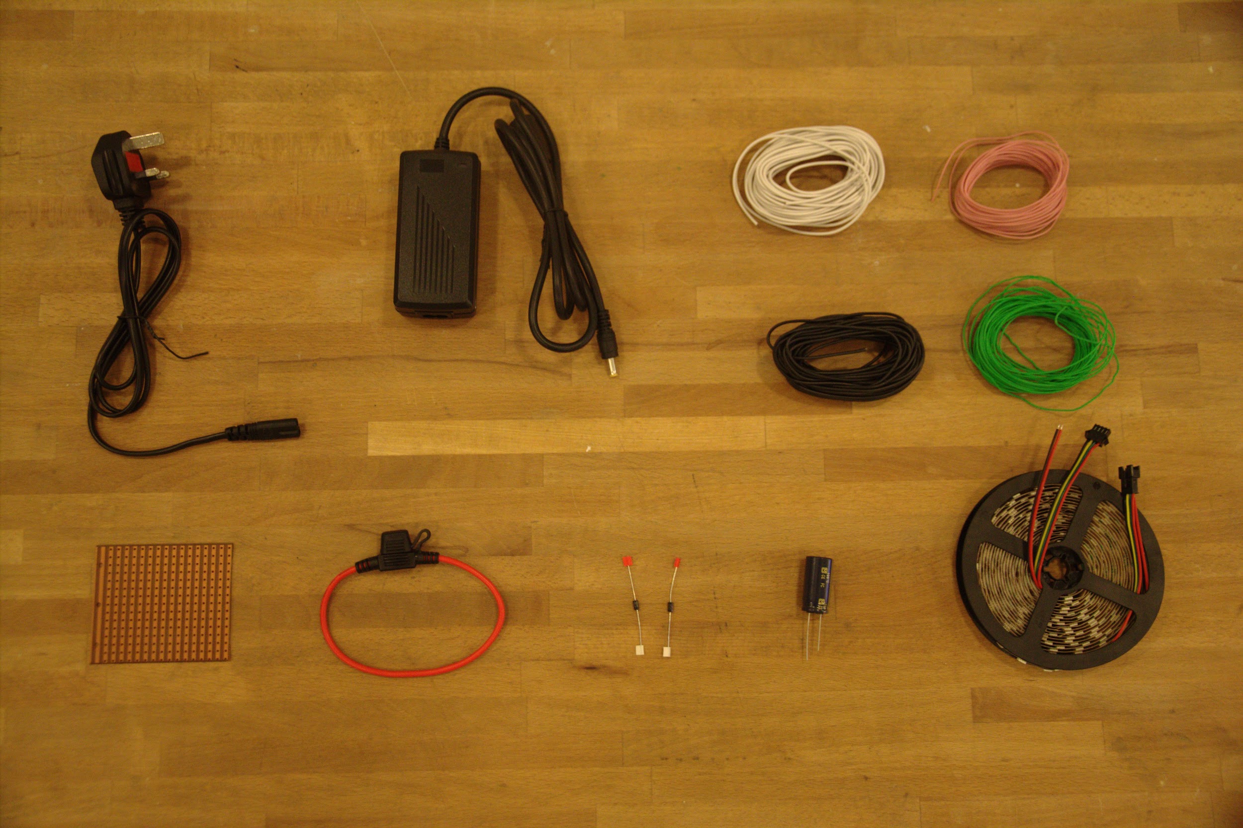 Prototype components: 5V 8A DC power adaptor, stripboard, wire, 7A automotive fuse w/ fuse
holder, 2 voltage regulators, 10,000μF capacitor and a 60LED/metre roll of addressable
APA102s, (not pictured:) Raspberry Pi, Arduino, USB cables, terminal block to connect the
power supply to, and a single LED + fuse to indicate power
Prototype components: 5V 8A DC power adaptor, stripboard, wire, 7A automotive fuse w/ fuse
holder, 2 voltage regulators, 10,000μF capacitor and a 60LED/metre roll of addressable
APA102s, (not pictured:) Raspberry Pi, Arduino, USB cables, terminal block to connect the
power supply to, and a single LED + fuse to indicate power
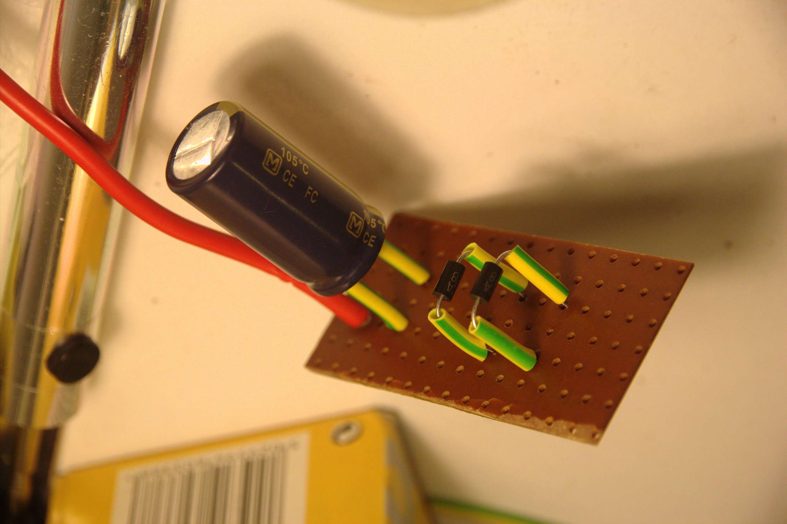 Voltage regulators and the capacitor soldered at a distance from the stripboard so they can be
easily desoldered to use in the final piece, with insulating sleeving to prevent a short circuit
Voltage regulators and the capacitor soldered at a distance from the stripboard so they can be
easily desoldered to use in the final piece, with insulating sleeving to prevent a short circuit
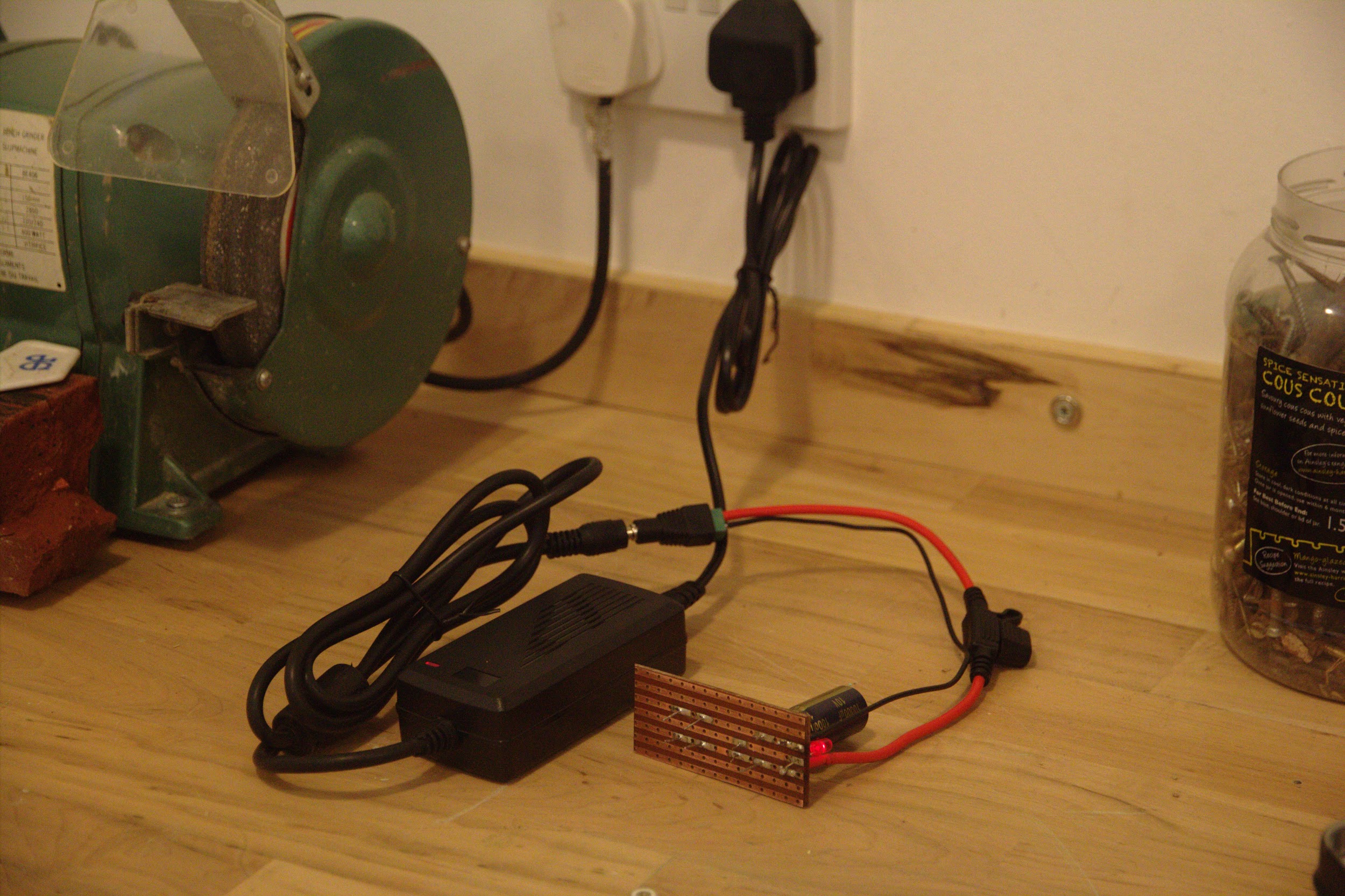 Testing power delivery with an LED on the splitboard indicating live rails
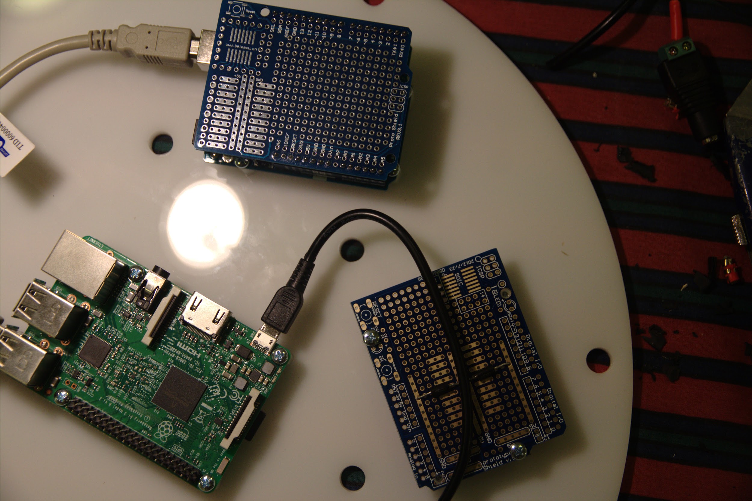
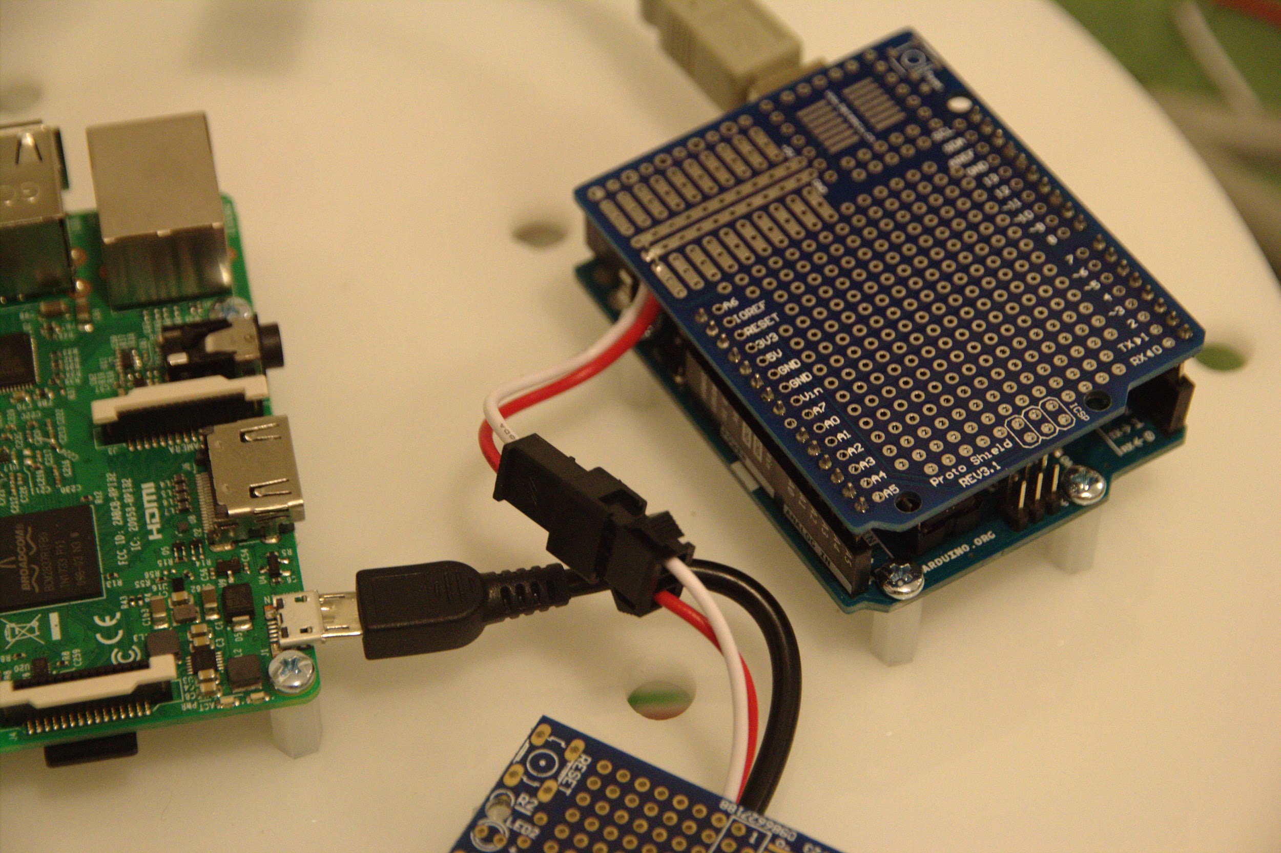
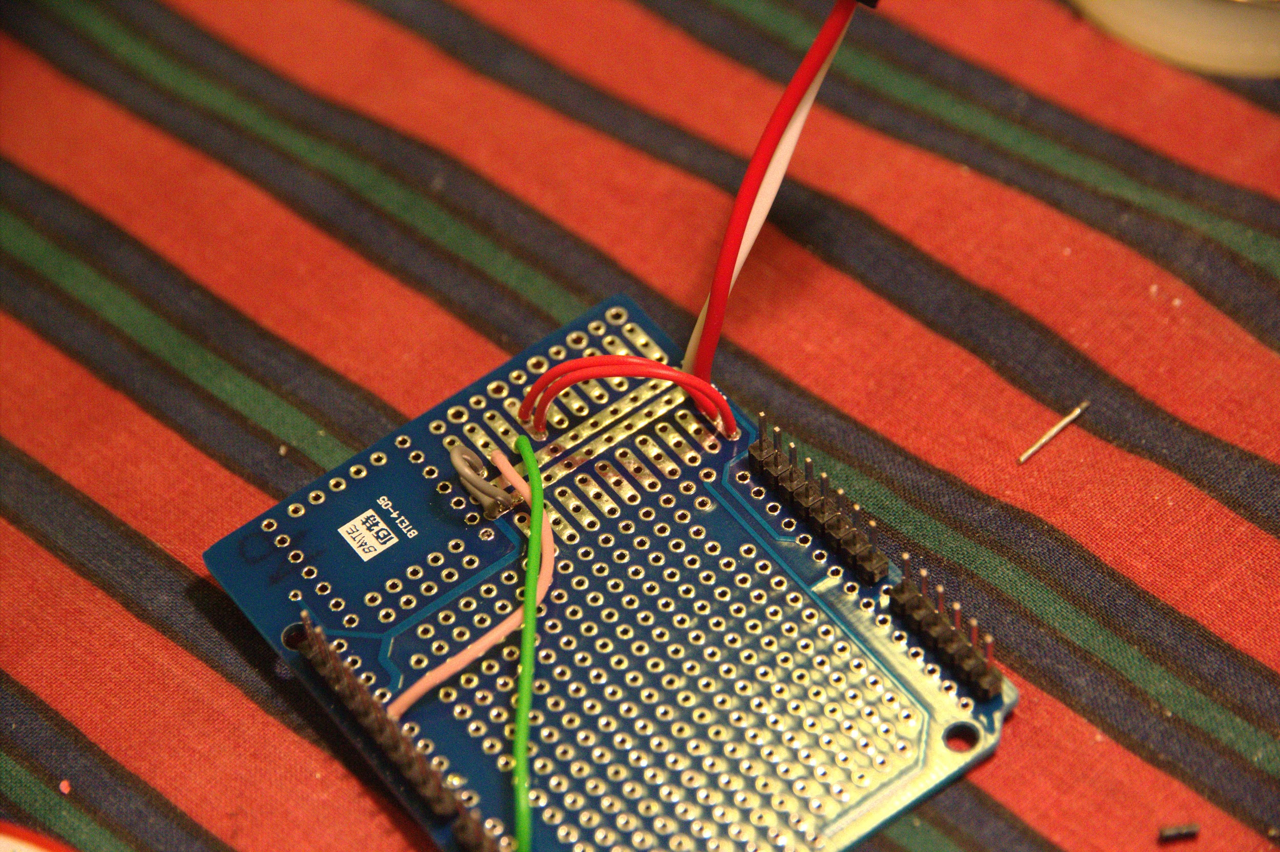
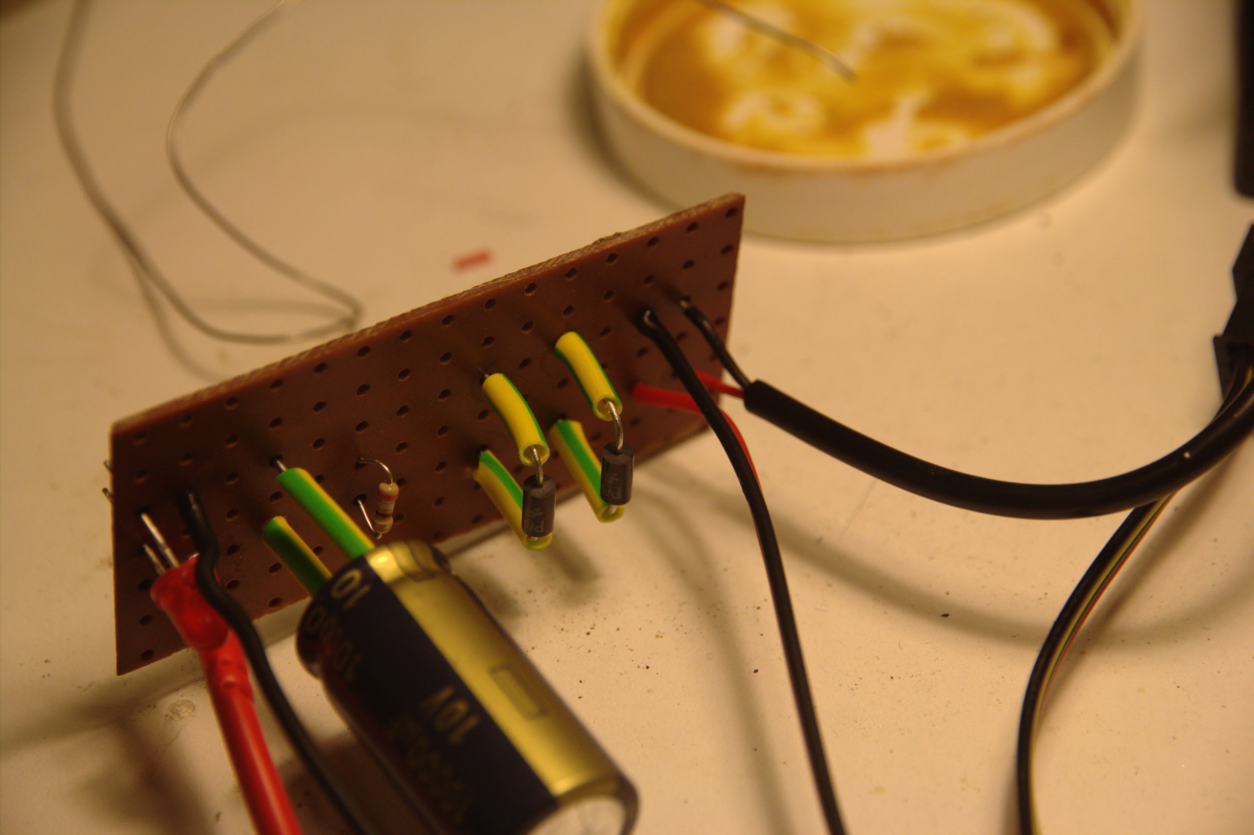 +5V and ground pairs (soldered on the right side of the stripboard) connecting to the RPi
MicroUSB and APA102 connector
+5V and ground pairs (soldered on the right side of the stripboard) connecting to the RPi
MicroUSB and APA102 connector
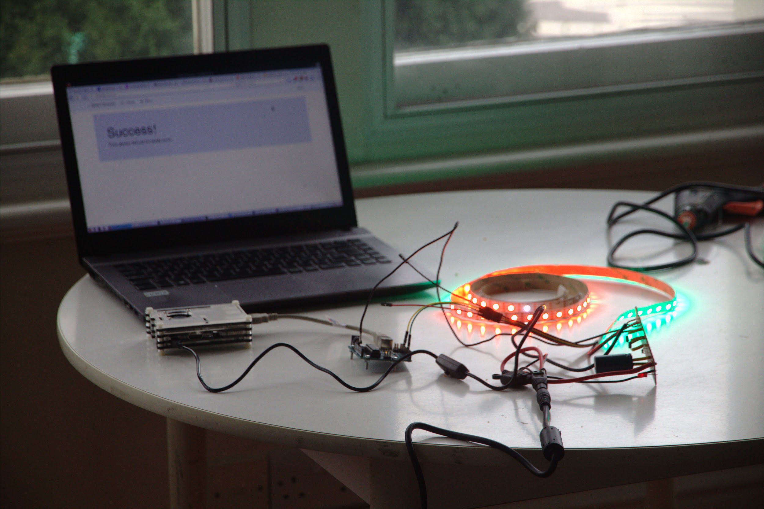 “Success!” with the strip lighting up after connecting the prototype splitboard, LEDs, Raspberry
Pi and Arduino together then compiling and uploading APA102 Arduino code
“Success!” with the strip lighting up after connecting the prototype splitboard, LEDs, Raspberry
Pi and Arduino together then compiling and uploading APA102 Arduino code
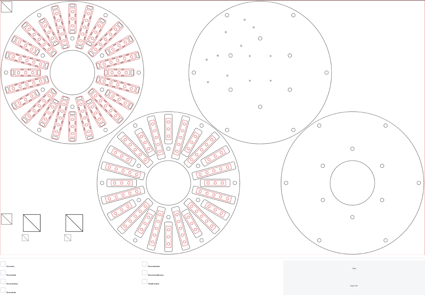 Web application developed for the final design showing the SVG above HTML inputs that
provide GUI access to basic functions
Web application developed for the final design showing the SVG above HTML inputs that
provide GUI access to basic functions
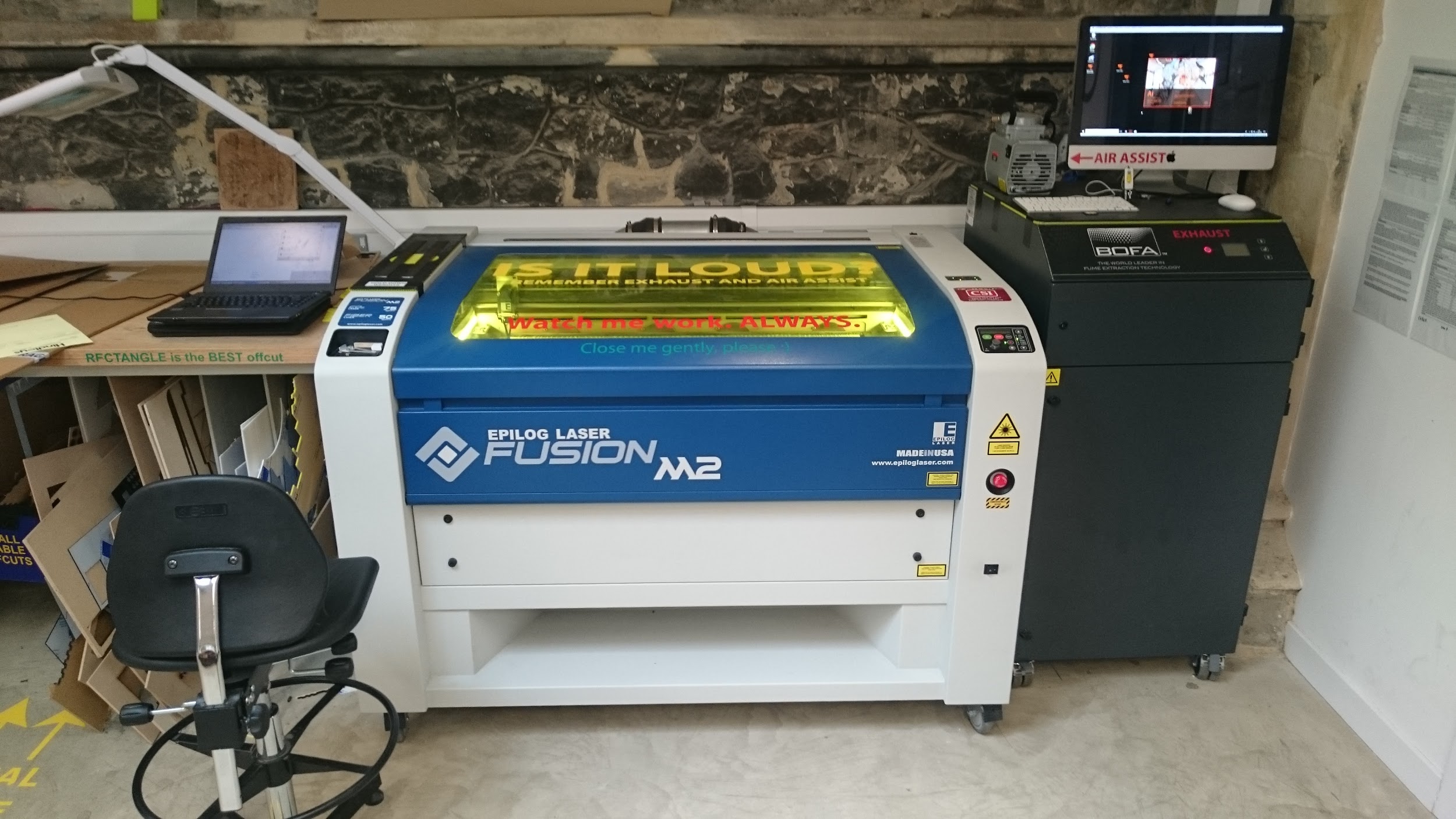 Laser cutting machine (centre) with the computer used to control it (right) and the project
development laptop (left)
Laser cutting machine (centre) with the computer used to control it (right) and the project
development laptop (left)
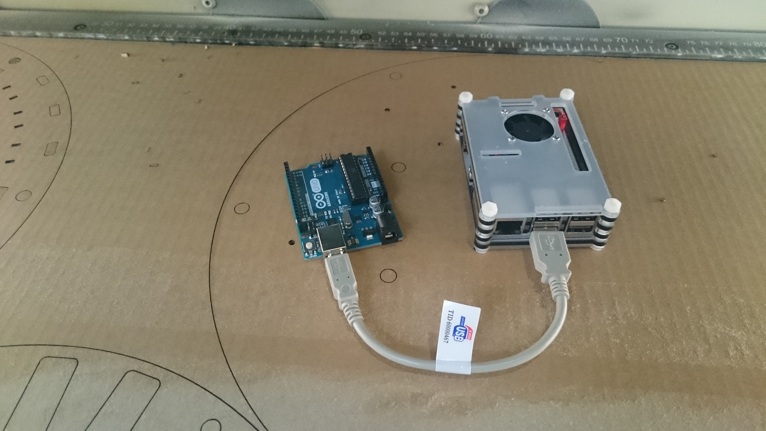 Checking the design’s scaling and measurement on cardboard using the Arduino and
Raspberry Pi
Checking the design’s scaling and measurement on cardboard using the Arduino and
Raspberry Pi
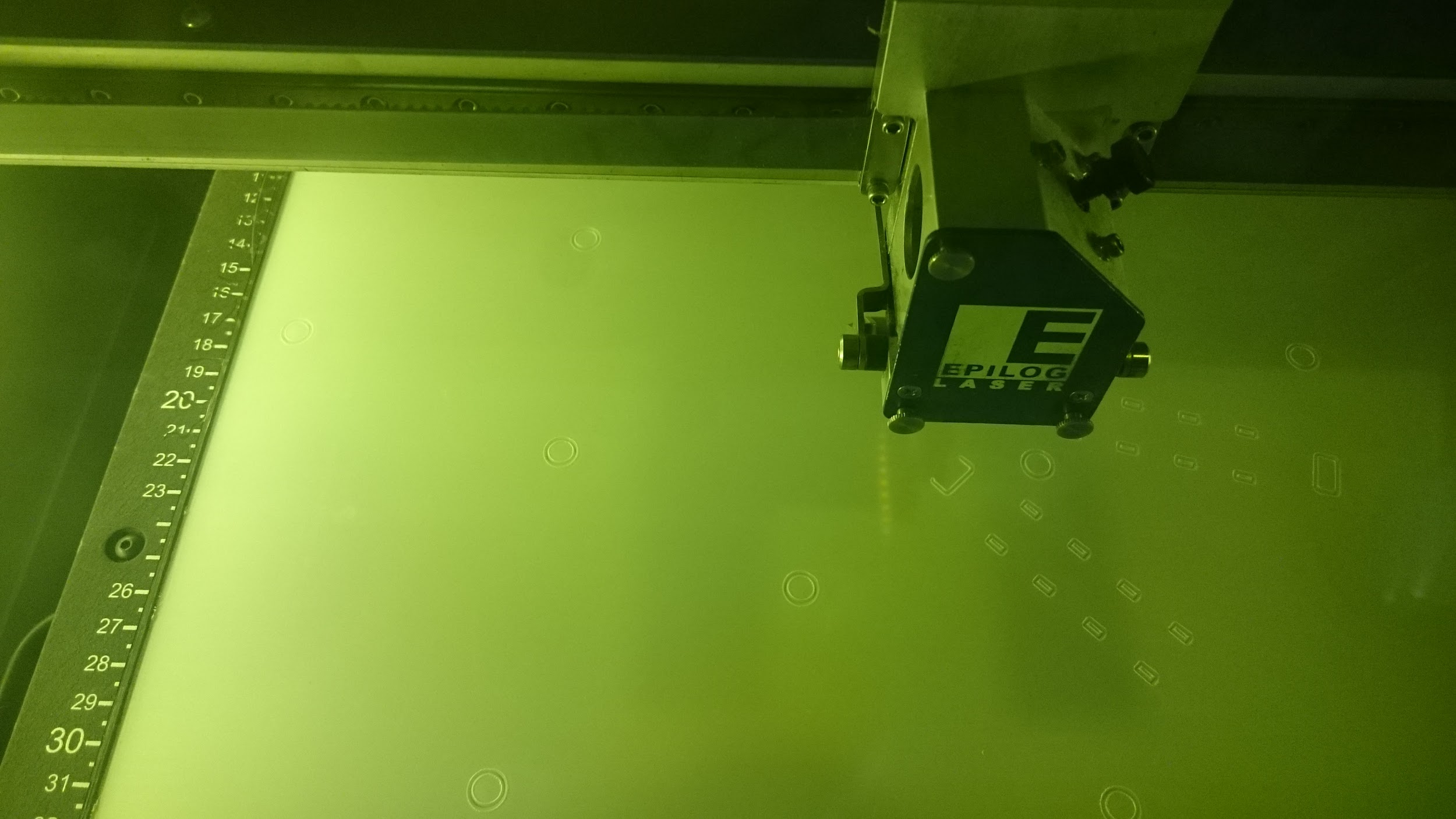 The first cable and bolt holes being laser cut out of Perspex
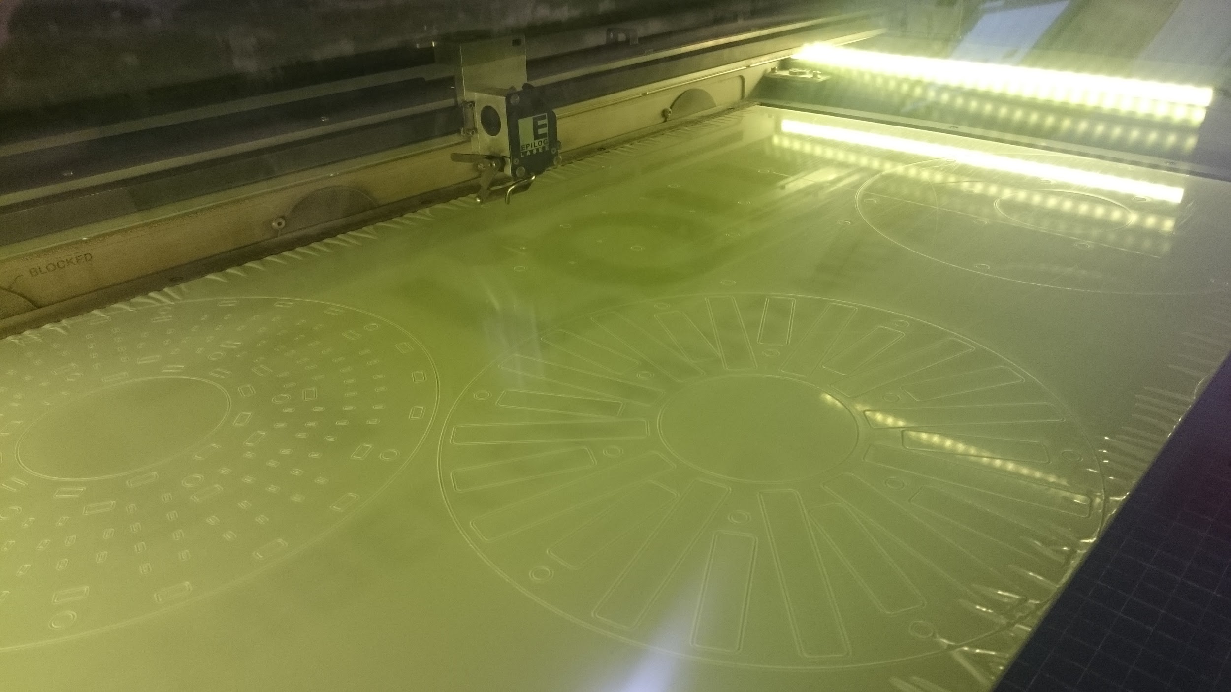 Towards the end of the laser cut process, it took over an hour in total
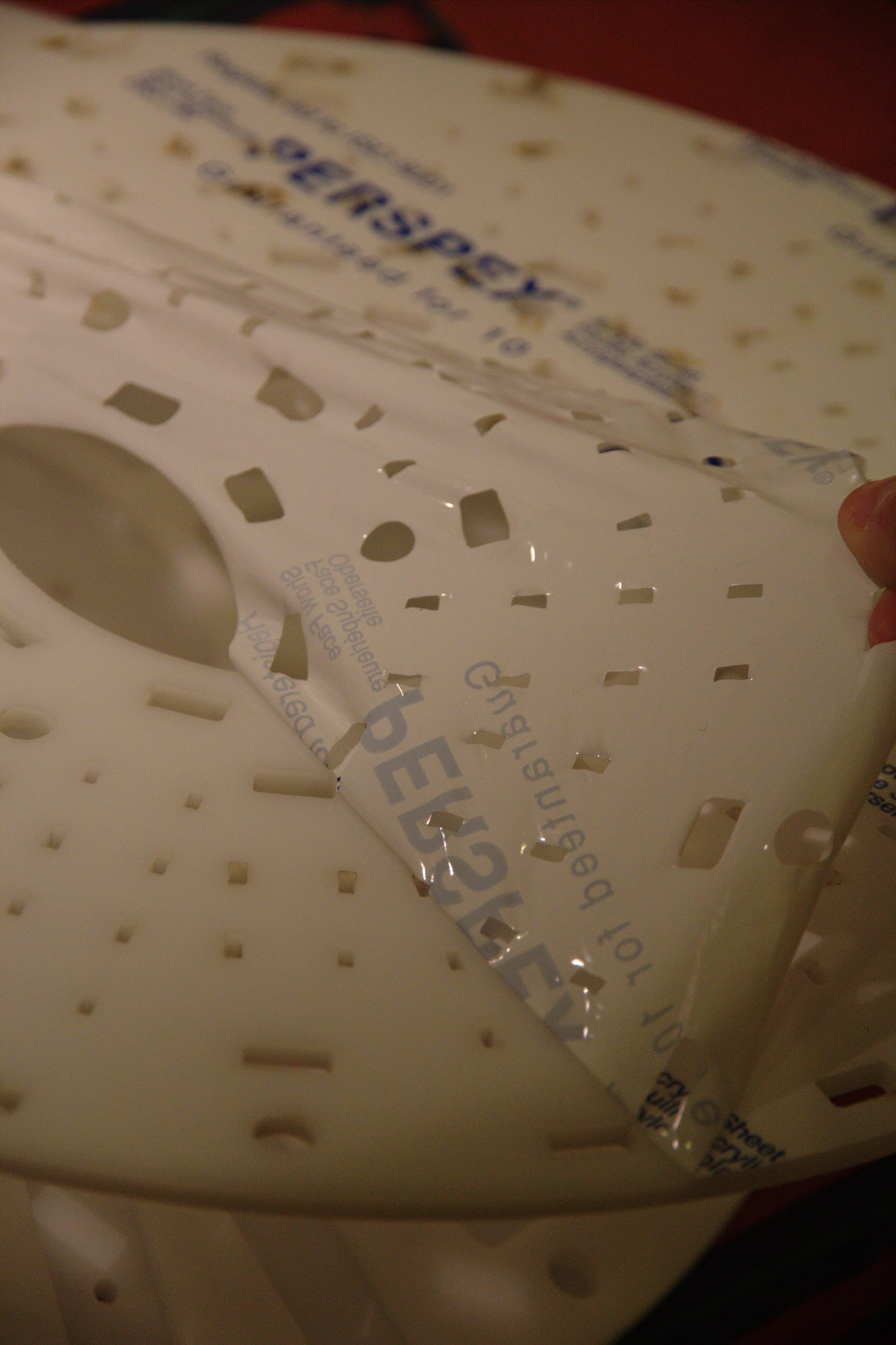 Peeling protective film off both sides of the Perspex
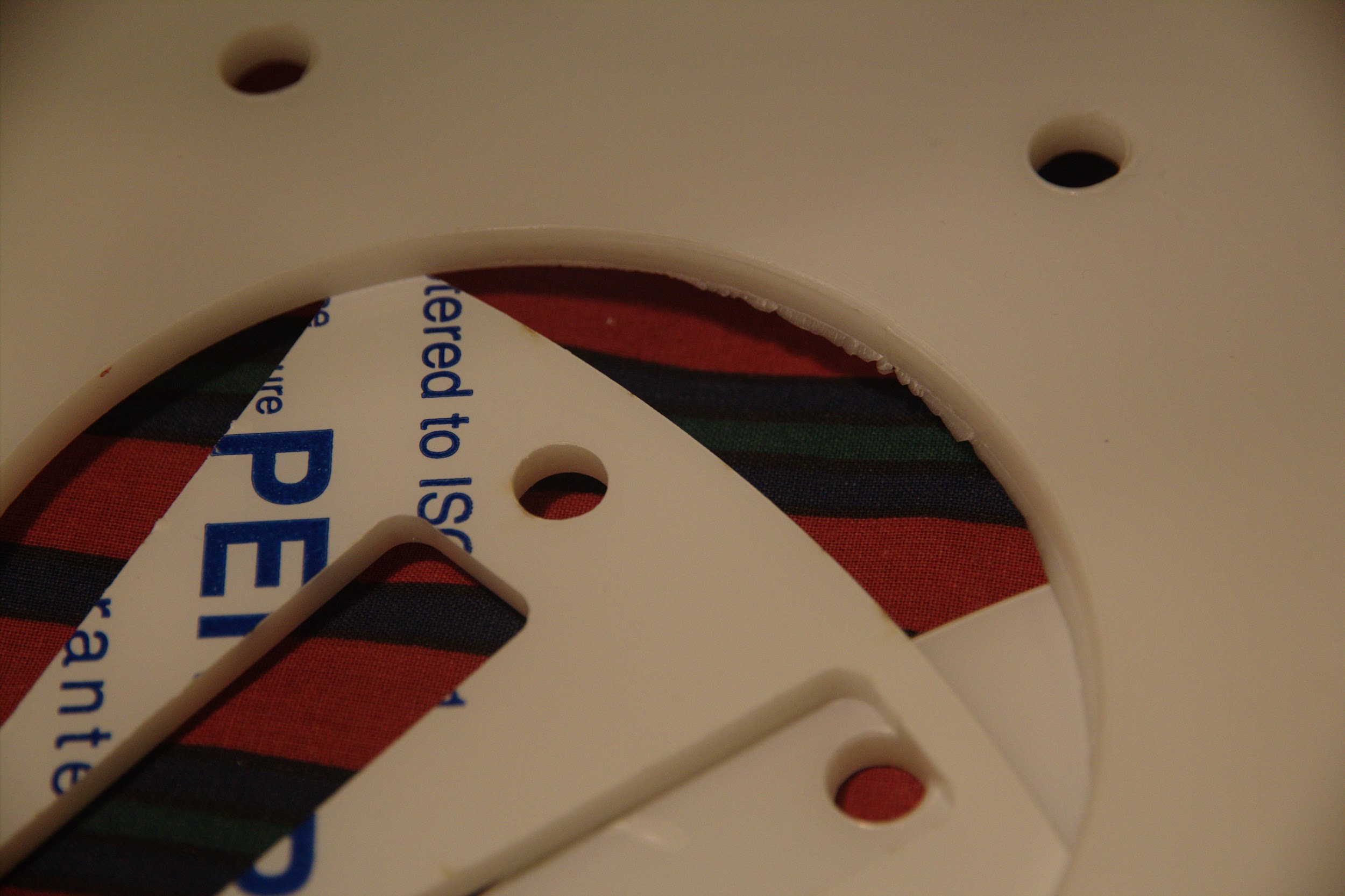 Sharp edges were leftover after detaching some pieces of acrylic (later filed down for safety)
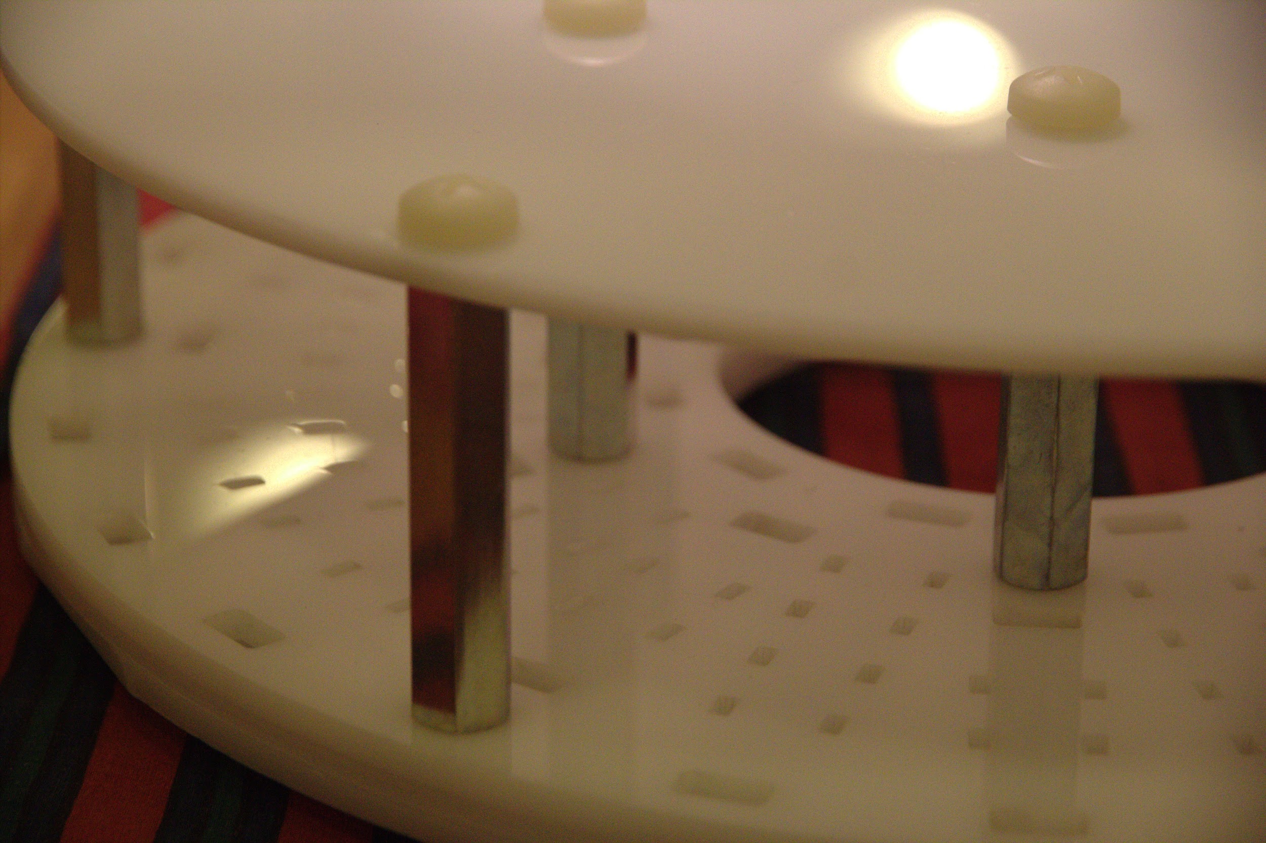
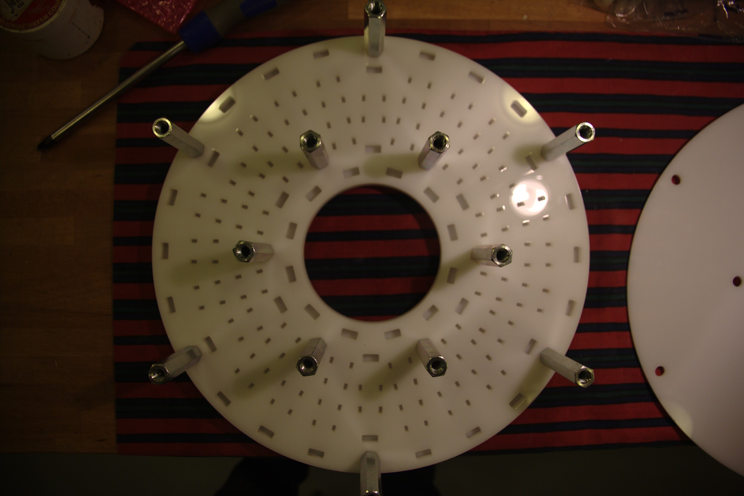 Checking the bolts fit securely through 3 pieces of Perspex into the spacers
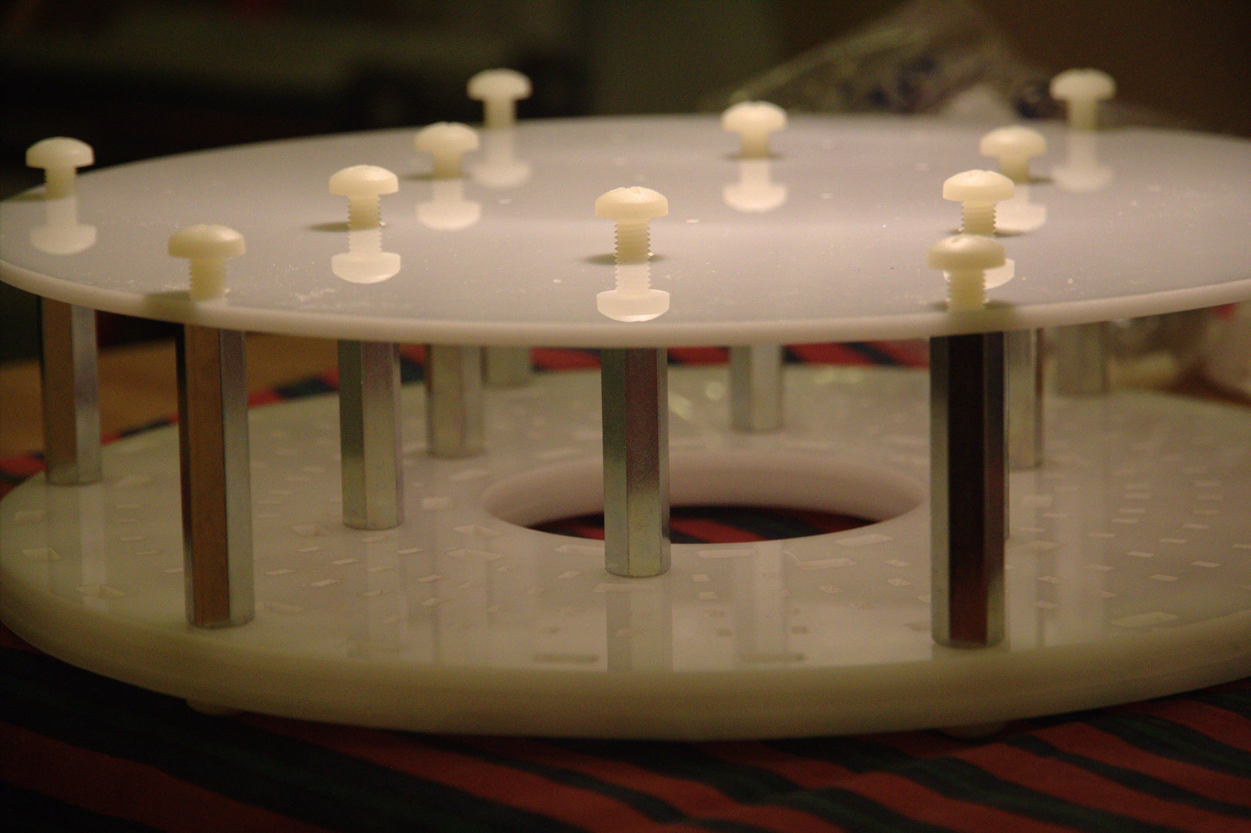 Bolts going through the single-layer side of Perspex screwed deeper into the spacers, resulting
in noticeably higher resistance/friction
Bolts going through the single-layer side of Perspex screwed deeper into the spacers, resulting
in noticeably higher resistance/friction
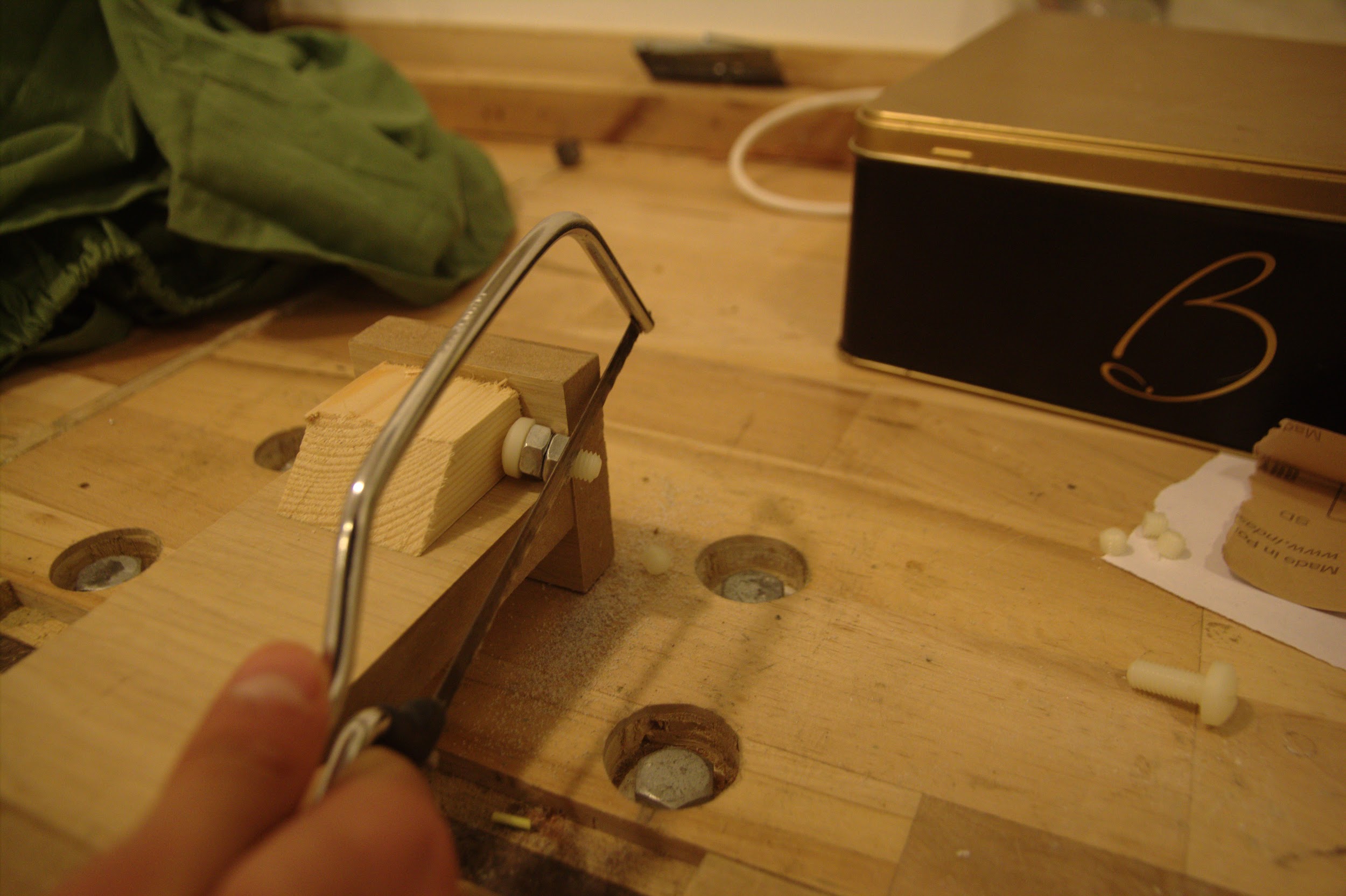 Sawing bolts to a shorter length to go through the single-layer side of Perspex
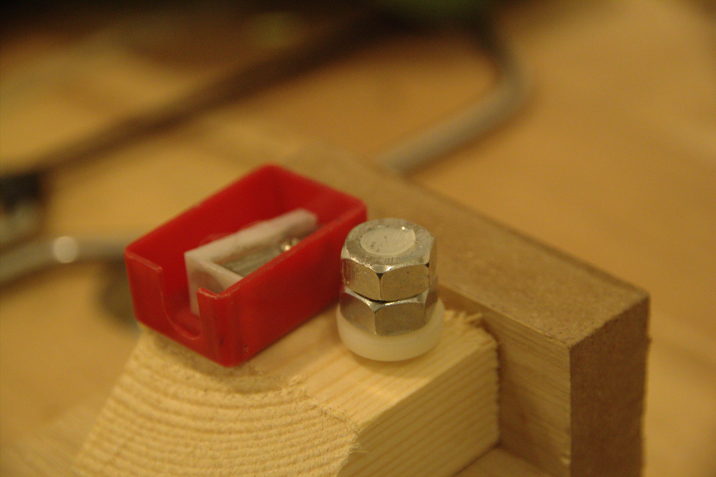 The bolts’ thread is initially damaged by the sawing process, unscrewing the nuts afterwards
helps to restore the original grooves
The bolts’ thread is initially damaged by the sawing process, unscrewing the nuts afterwards
helps to restore the original grooves
 The shortened bolts secure into the spacers more easily
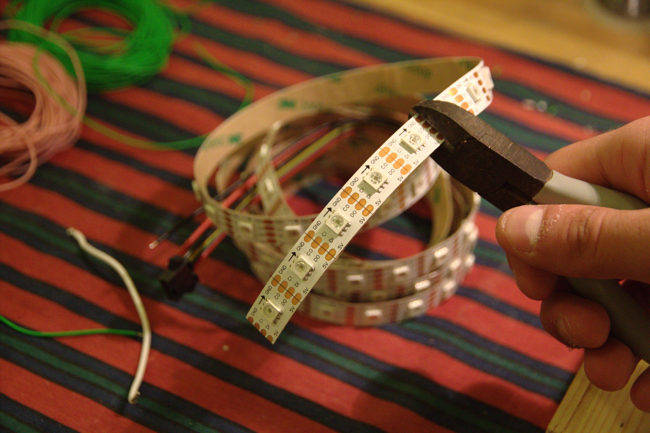 Cutting the first strip of 5 LEDs off the PCB reel
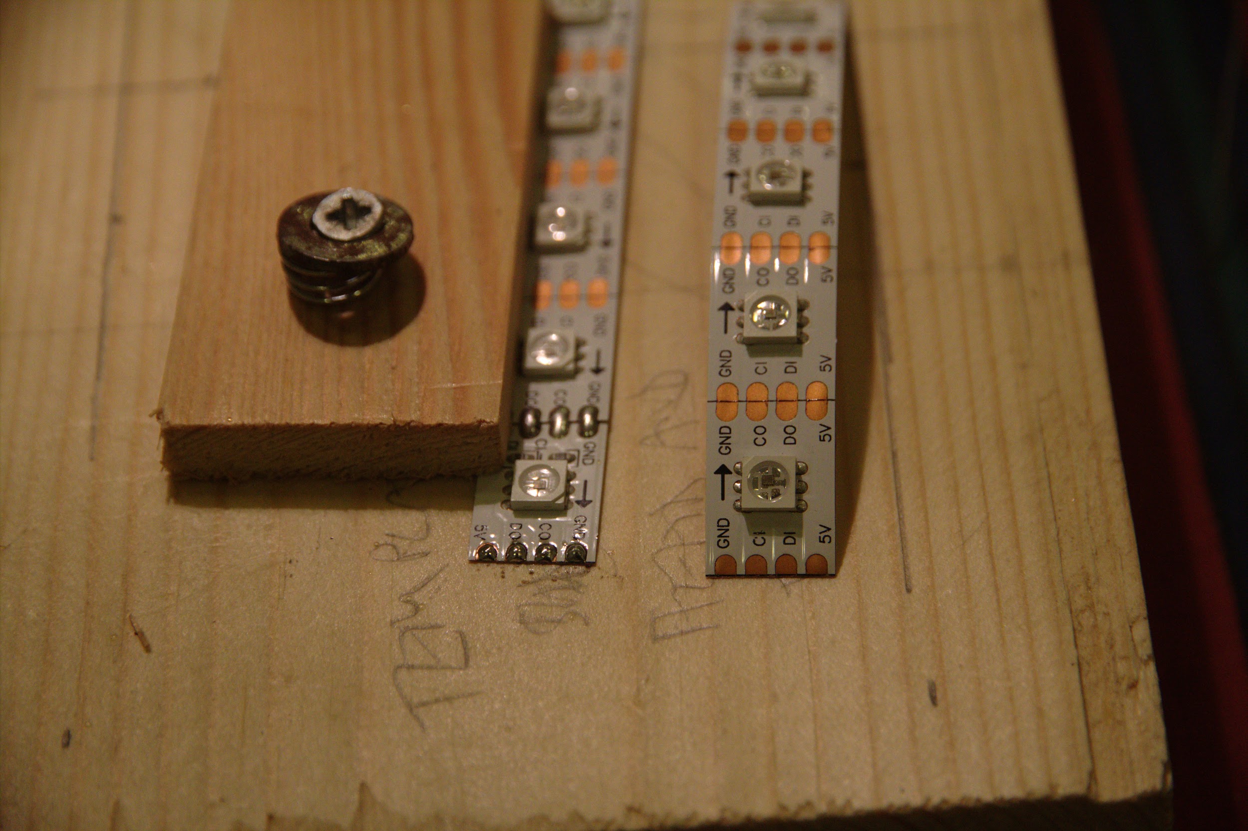 Comparison of tinned and untinned connections (left and right respectively), it helps to prepare
these on a rig that is less fiddly than the Perspex strip holder
Comparison of tinned and untinned connections (left and right respectively), it helps to prepare
these on a rig that is less fiddly than the Perspex strip holder
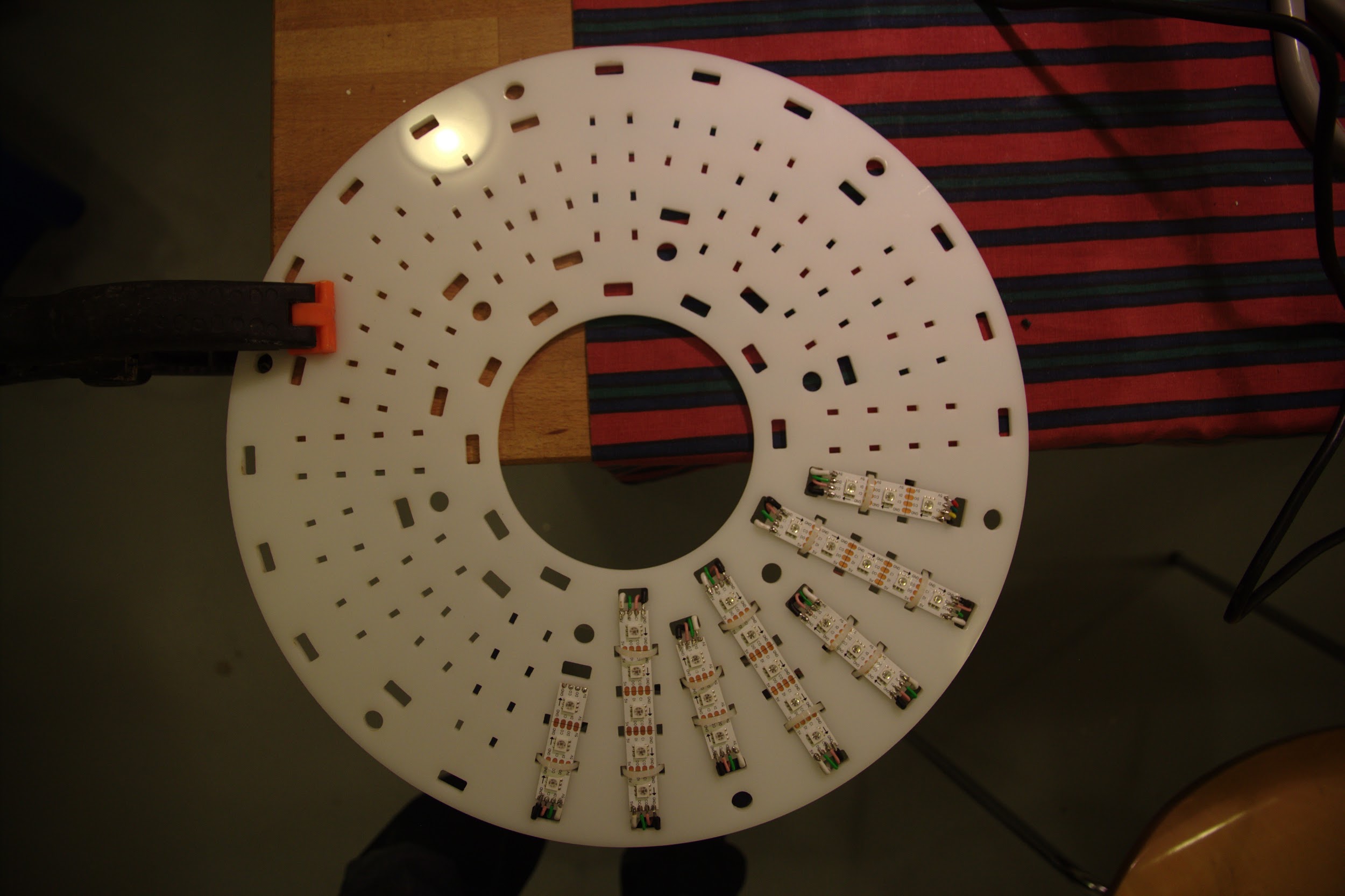
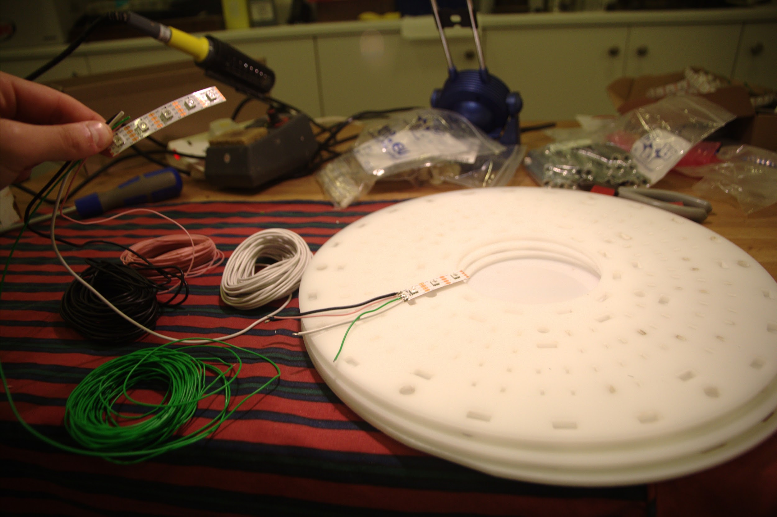 A small number of strips were attached to begin with, so the technique could be improved
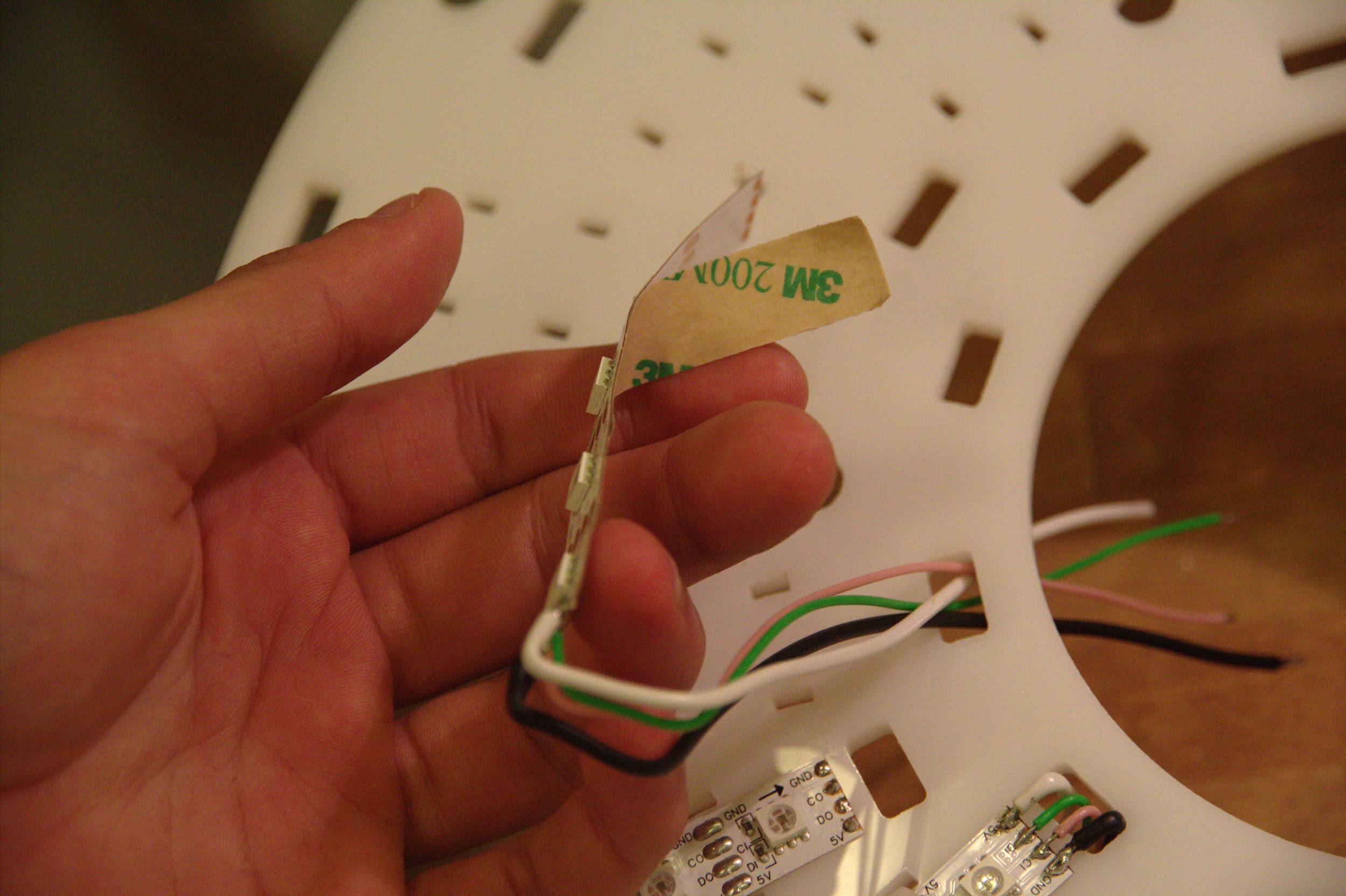 Peeling adhesive tape off the bottom of the strip in order to stick them to the Perspex
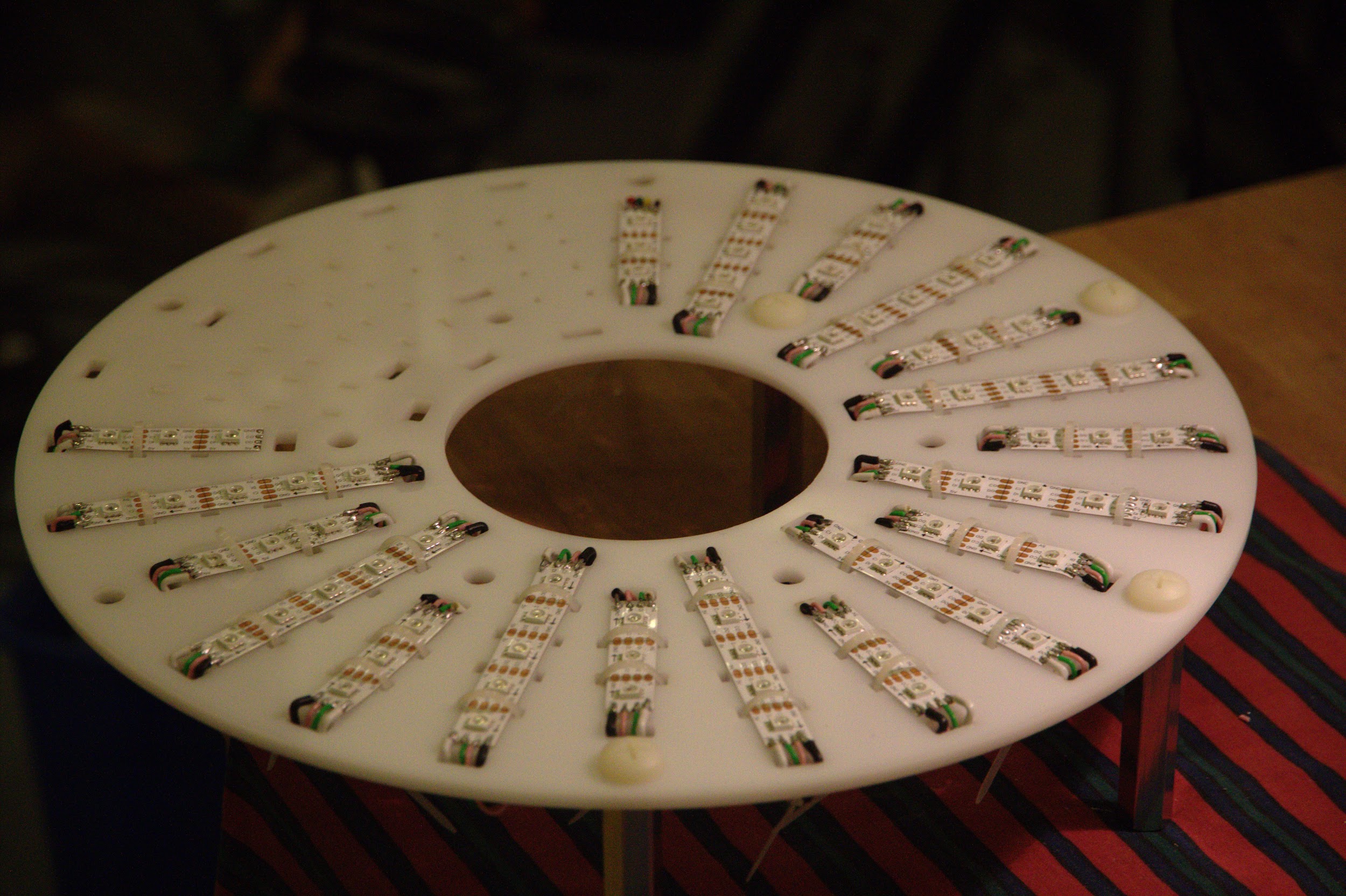
 After the adhesive, zip-ties secure the strips to the Perspex and help manage the wires below
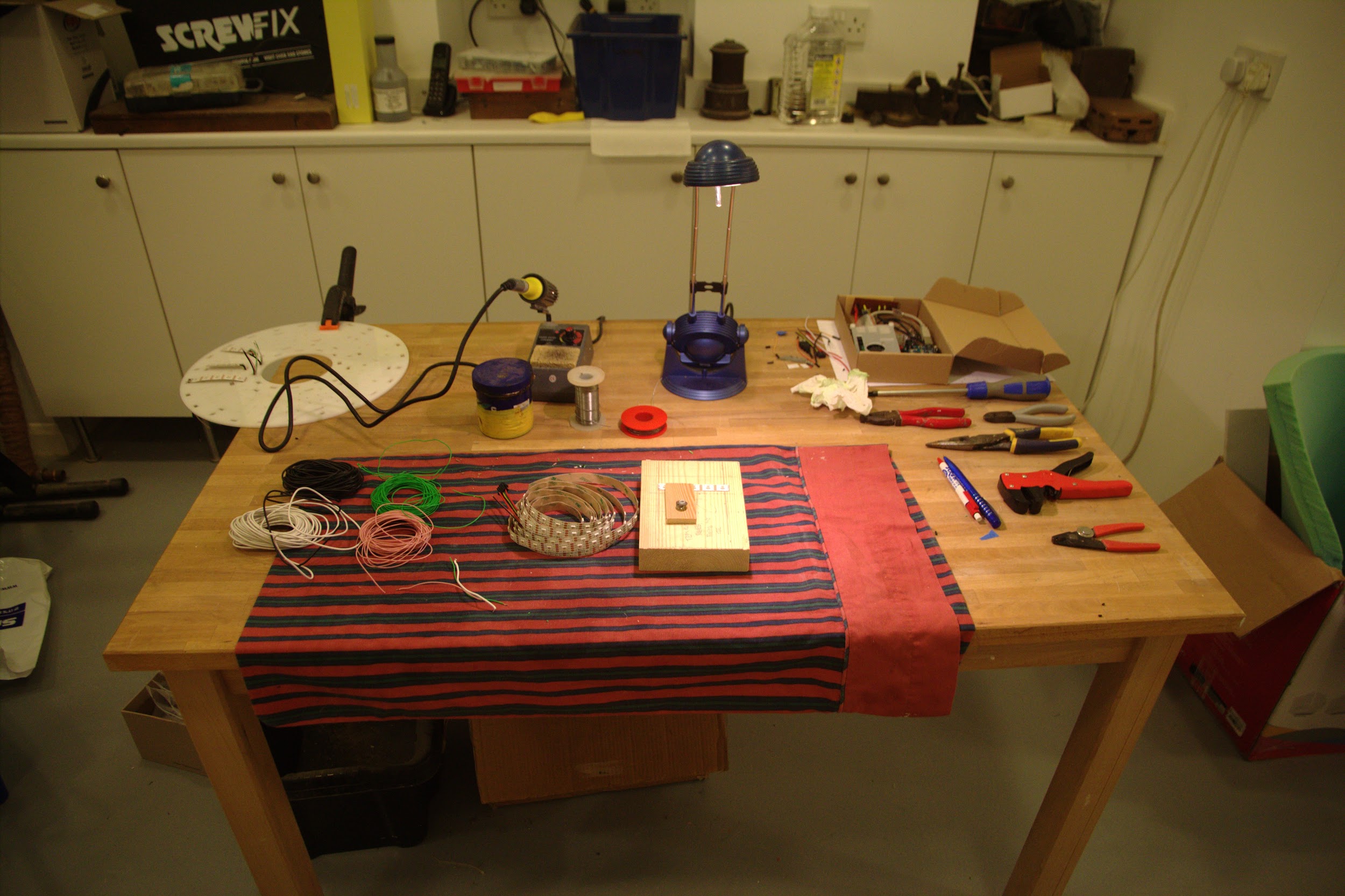 Setup to cut and pre-solder LED strip and wire for more segments of the physical piece
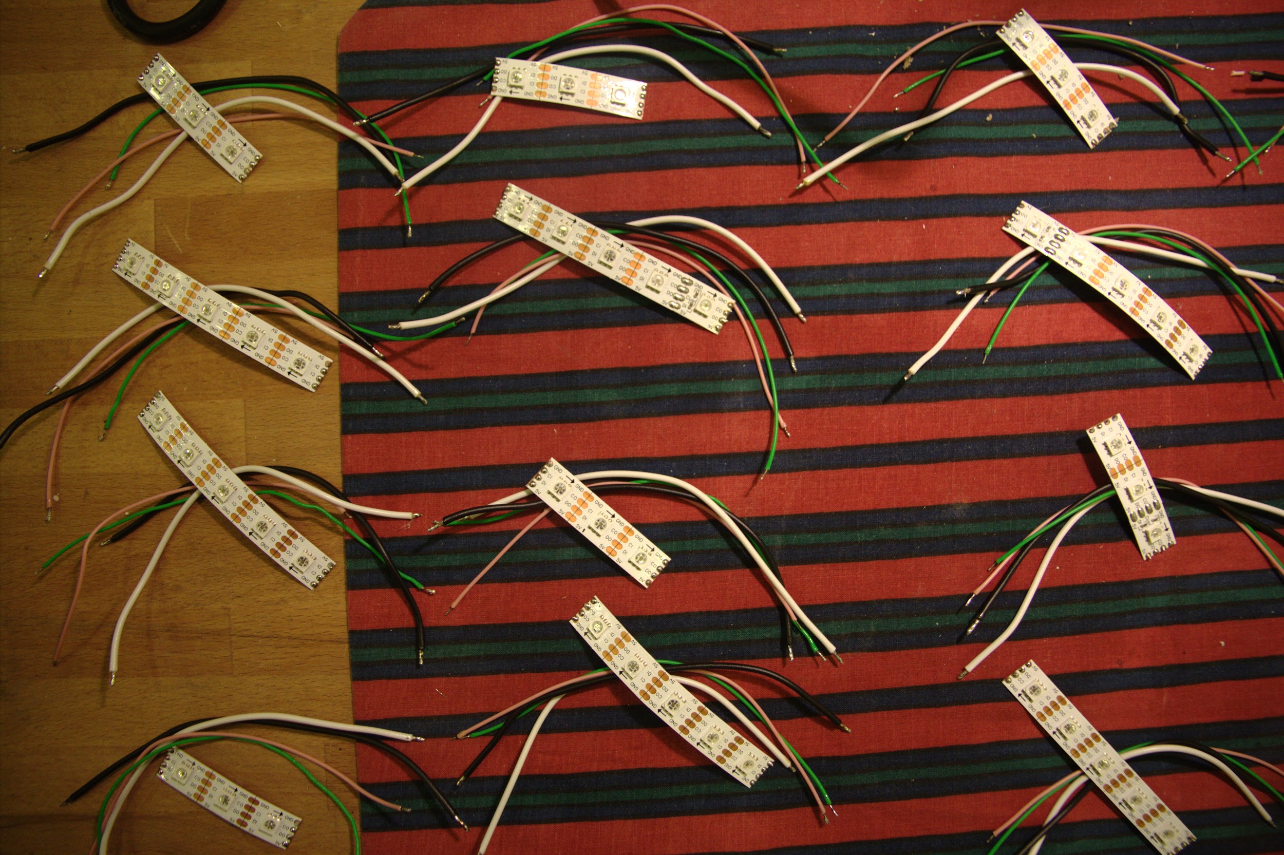 Prepared segments after stripping the wires, twisting the stranded ends to avoid fraying and
tinning the connections
Prepared segments after stripping the wires, twisting the stranded ends to avoid fraying and
tinning the connections
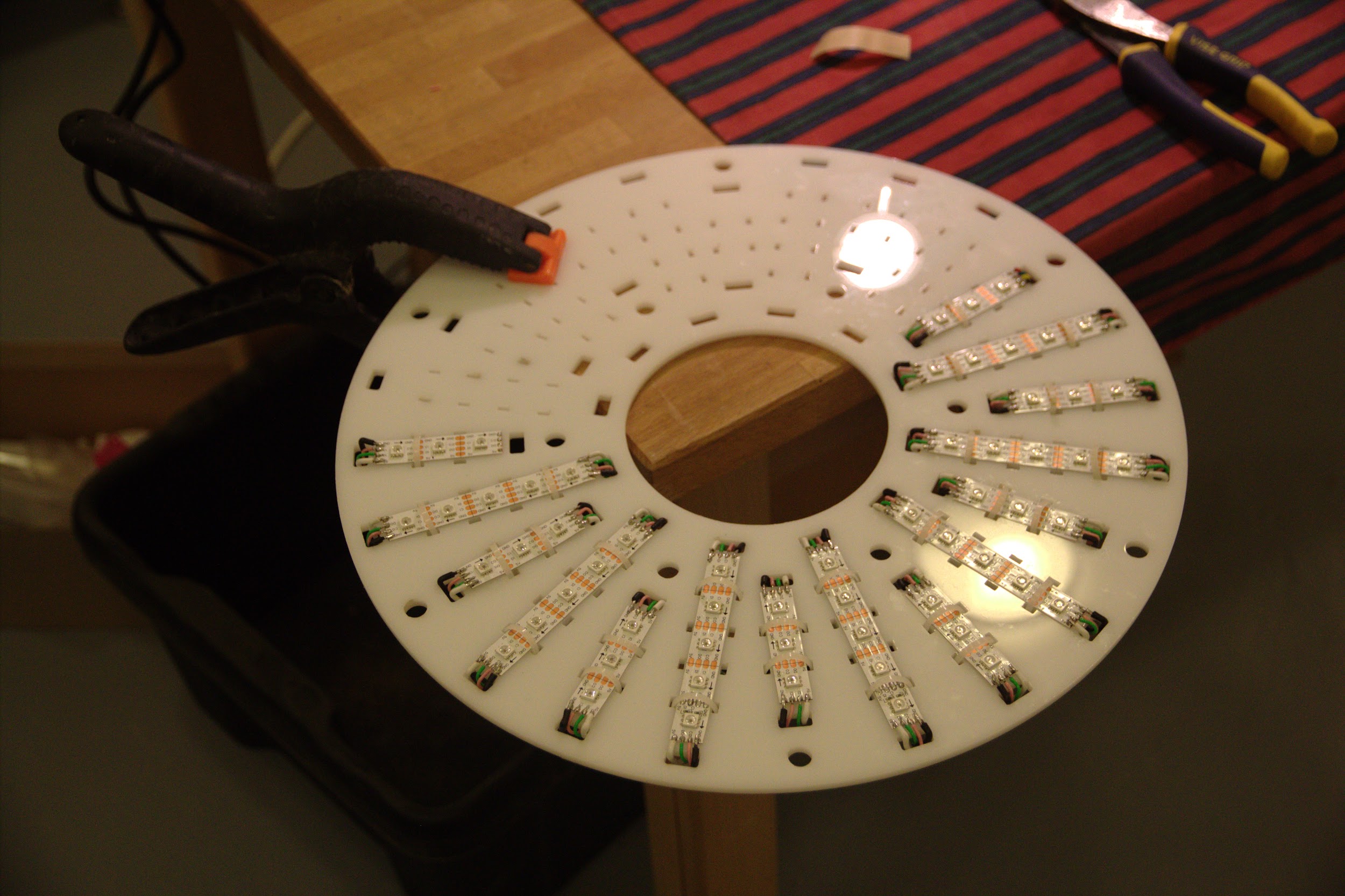
 The LED-bearing Perspex after a quarter of the strips were attached
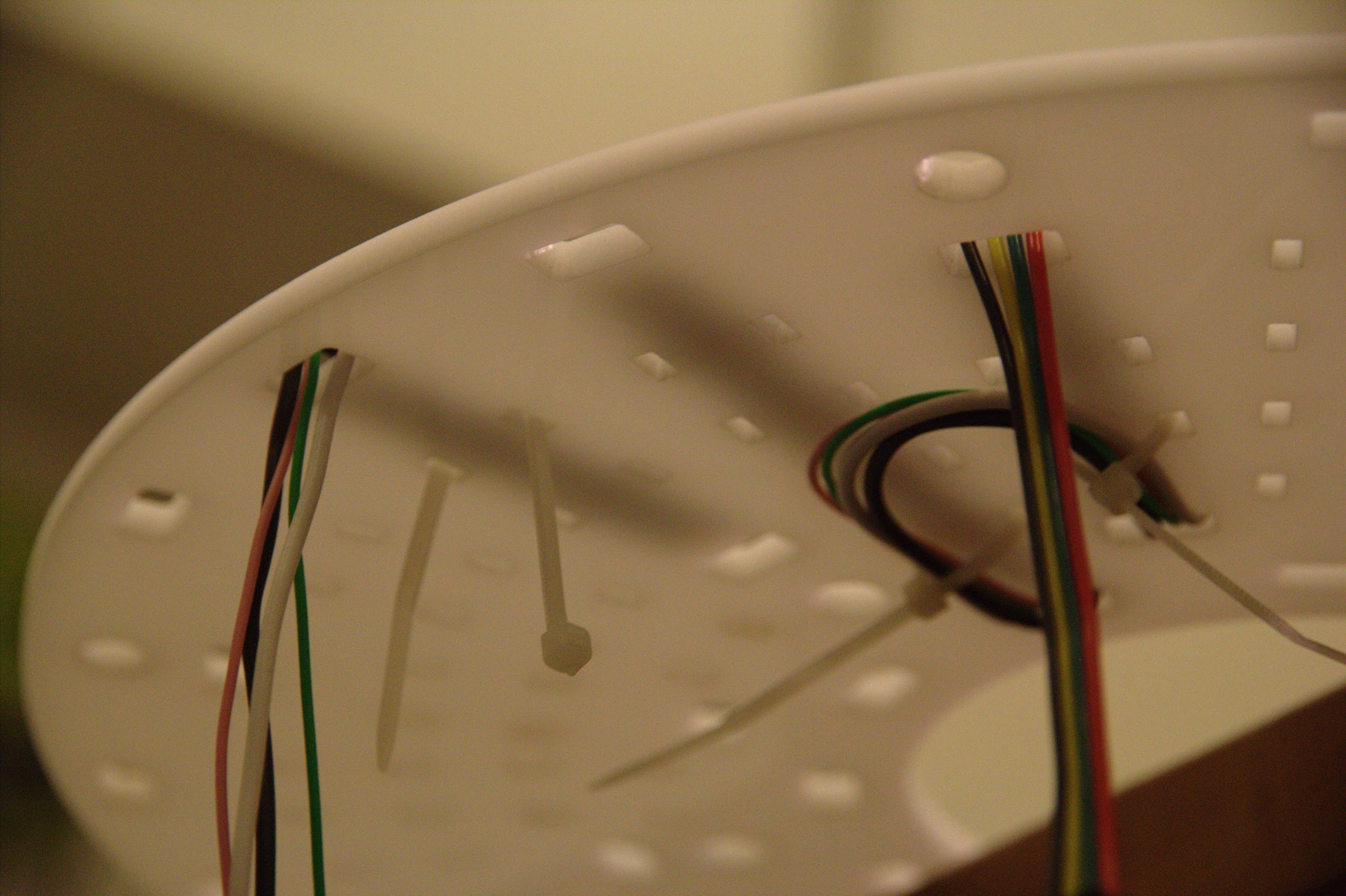
 Wires linking each segment of LED strip to the next are routed through zip ties below the acrylic
 The Perspex was moved around the corner of the table when strips went over halfway around
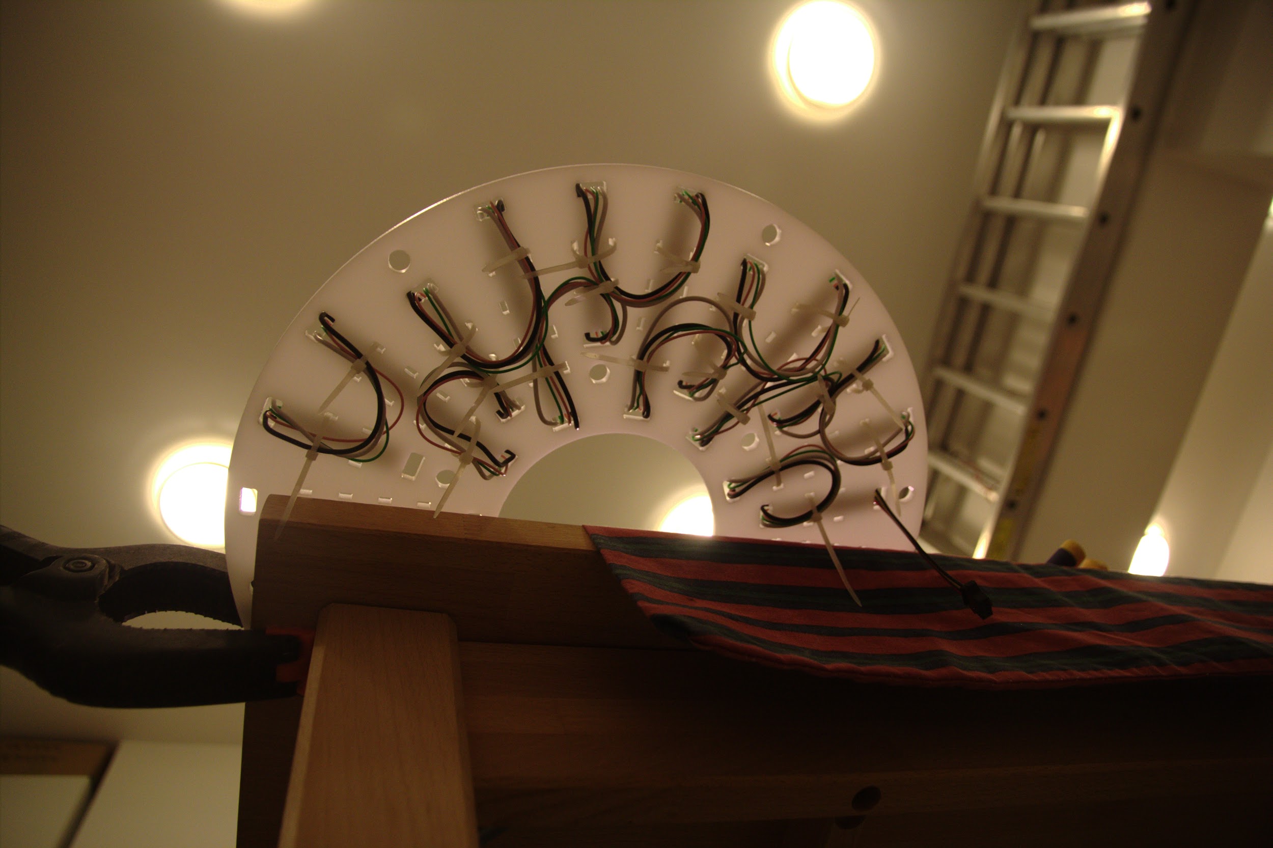
 Accessing the top and bottom of the Perspex, in order to attach the remaining segments, was
achieved after unclamping it from the tabletop by connecting a number of spacers it could
balance on
Accessing the top and bottom of the Perspex, in order to attach the remaining segments, was
achieved after unclamping it from the tabletop by connecting a number of spacers it could
balance on
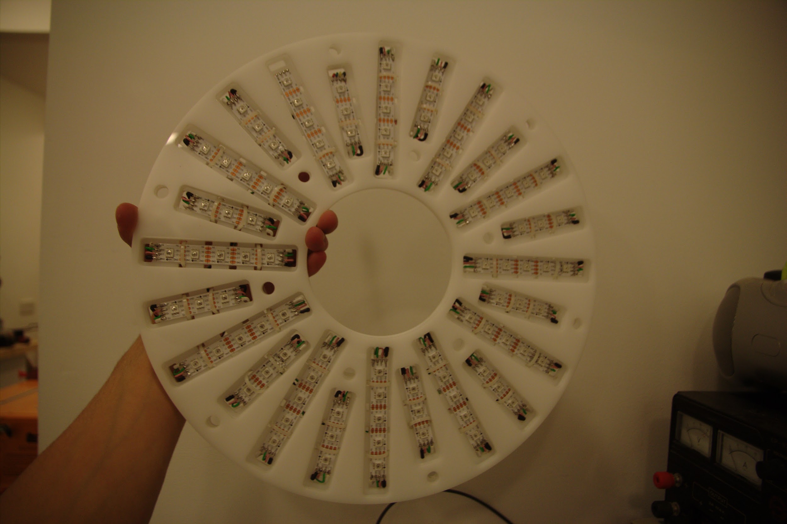 The upper sections after all the LED strips were connected
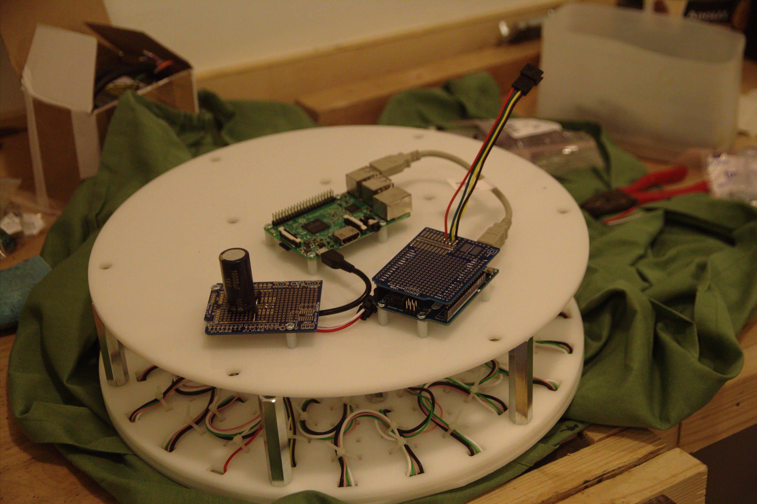
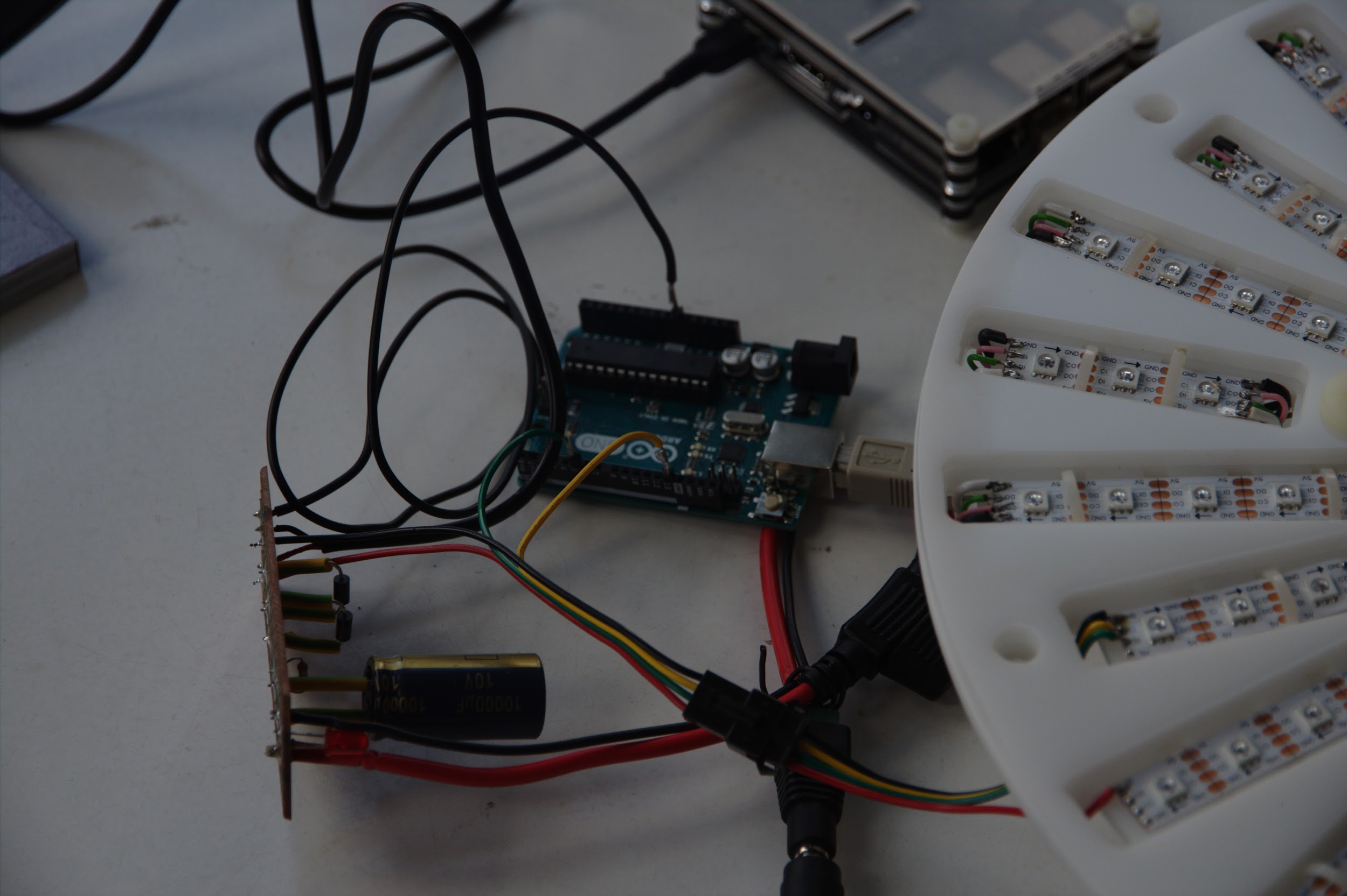 Electronics from the prototype hooked up to the new newly finished LED-plate
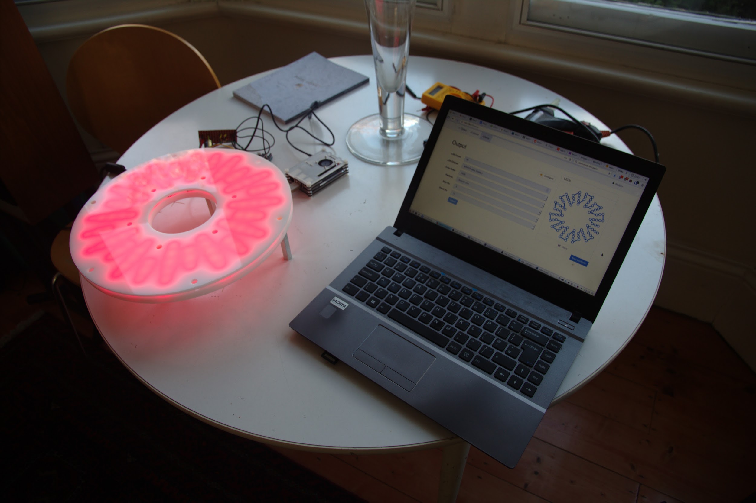 Lighting up the configured display for the first time to check it works
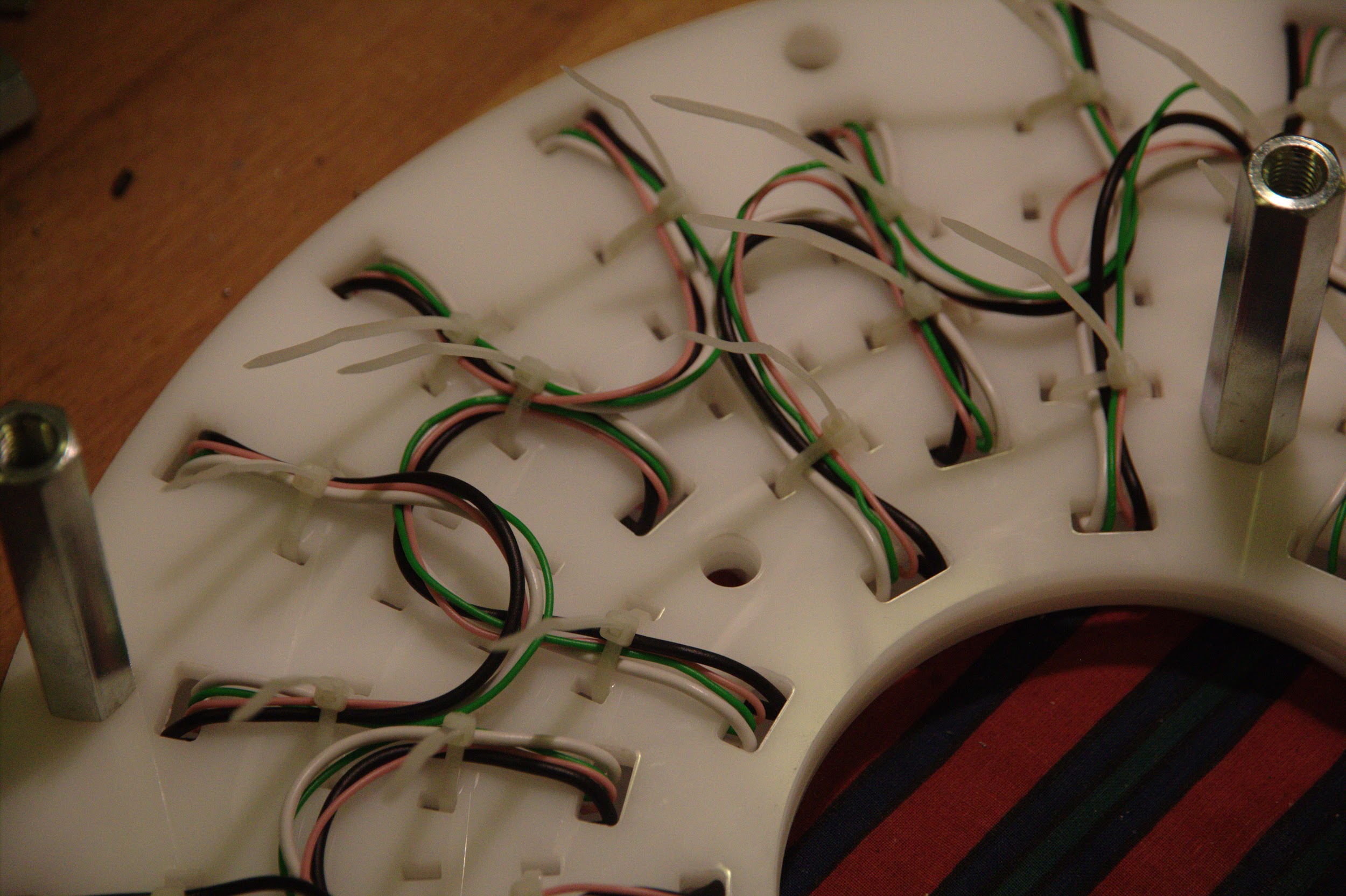 Tightened zip ties on the component’s underside
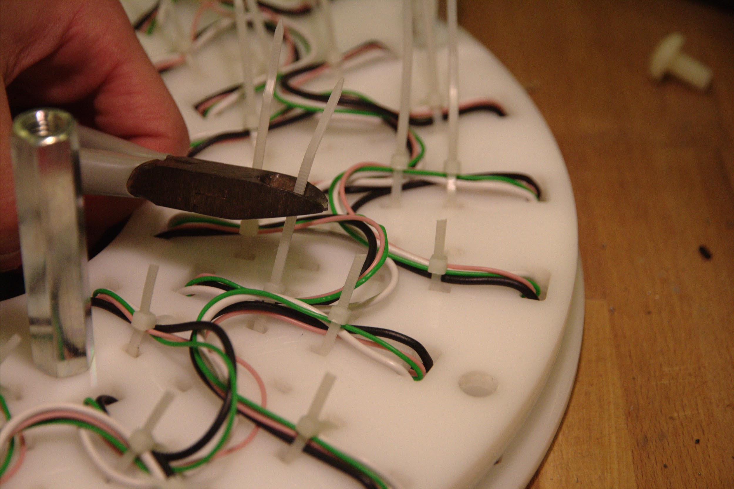 Clipping excess plastic off the secured zip ties to make space for parts to fit below
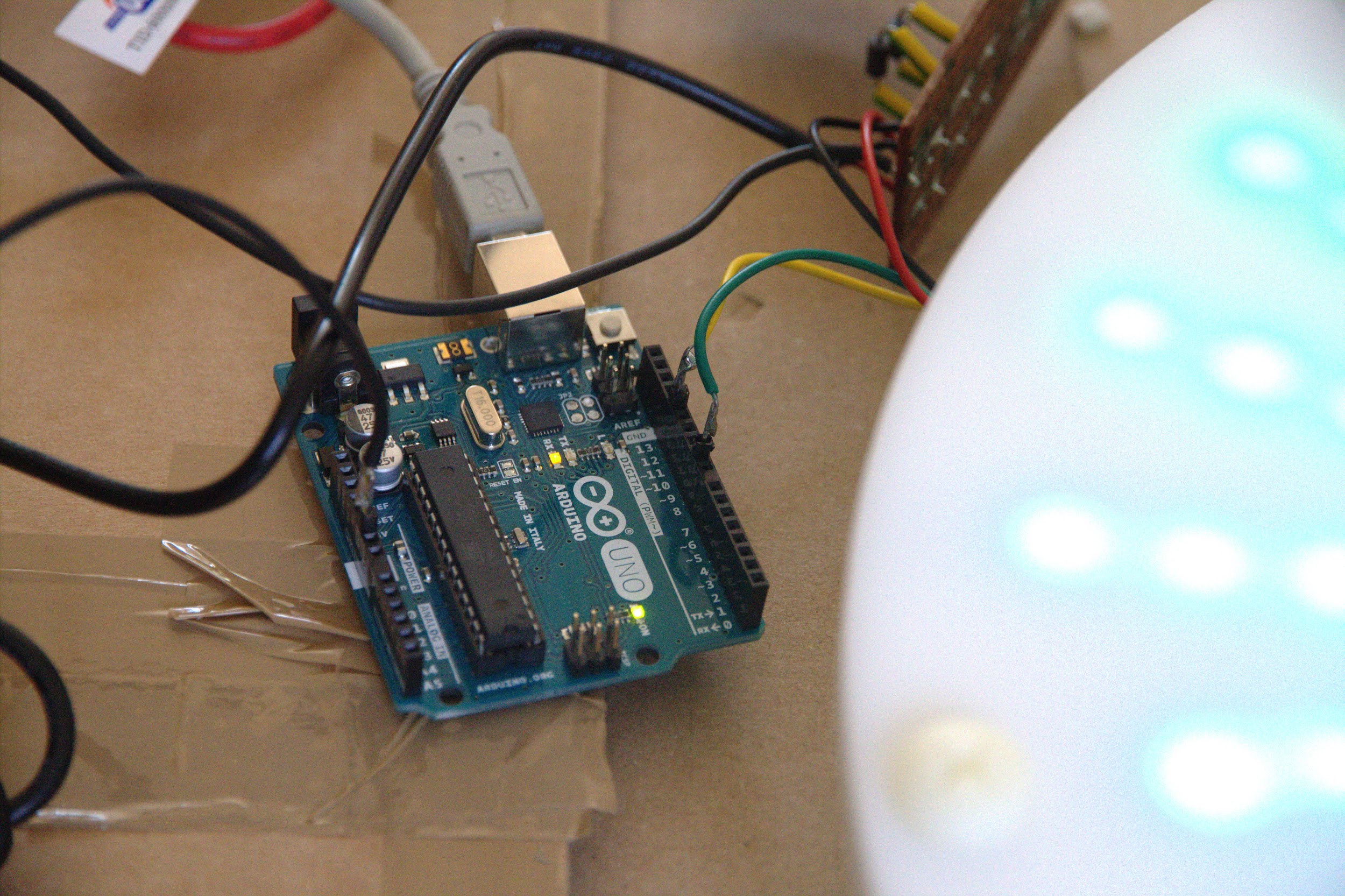 Experiment to control the LEDs using previously untested Arduino pins for data and clock,
knowing they worked gave more flexibility in the upcoming circuit design
Experiment to control the LEDs using previously untested Arduino pins for data and clock,
knowing they worked gave more flexibility in the upcoming circuit design
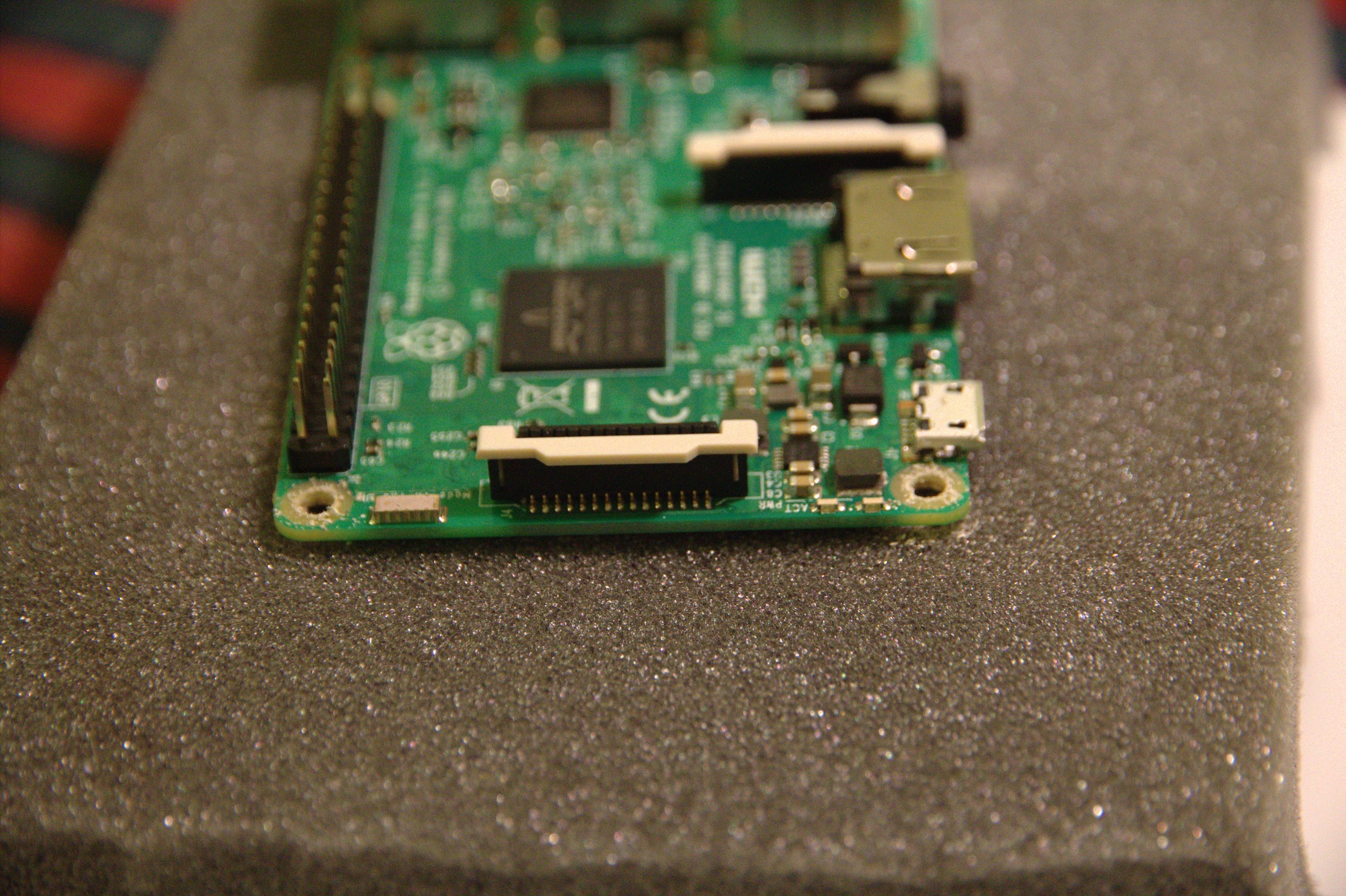
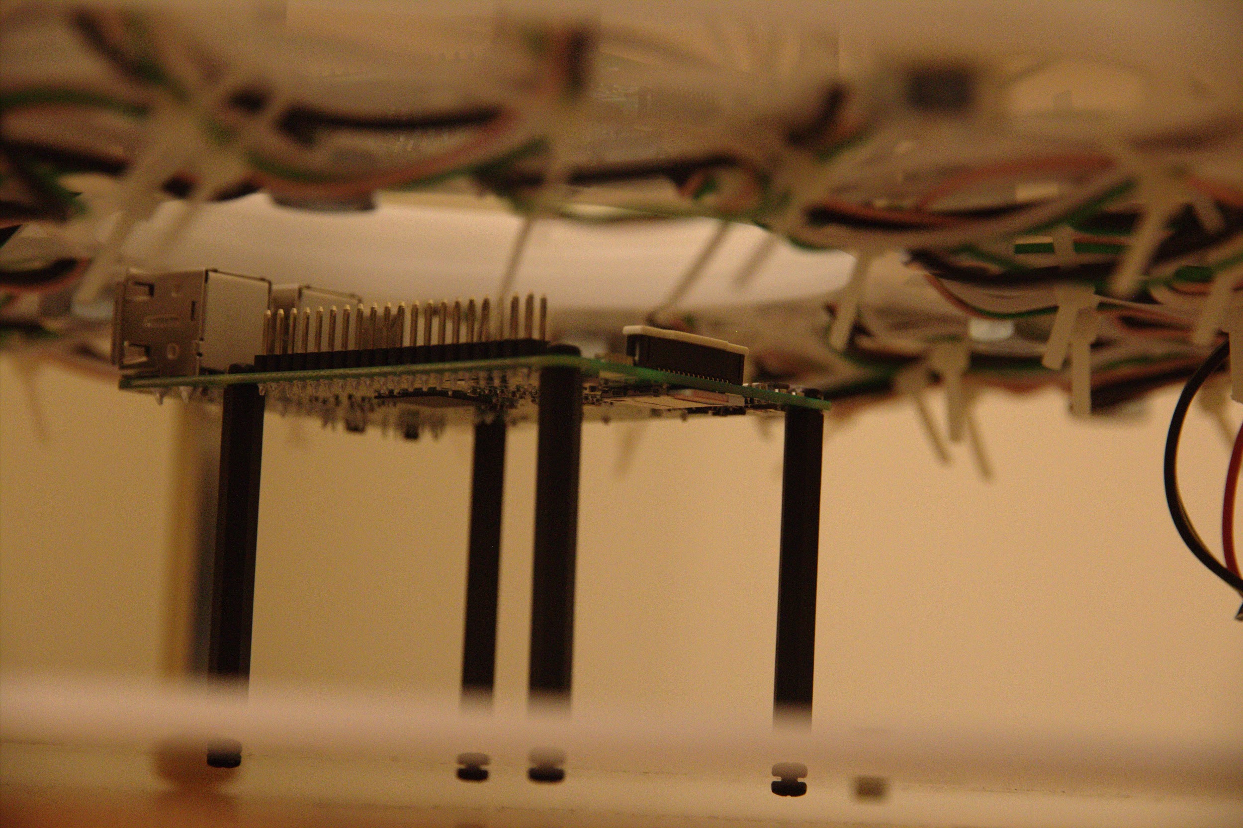 The originally planned RPi mounting solution brought the Pi close to the LEDs but held it weaker
in position
The originally planned RPi mounting solution brought the Pi close to the LEDs but held it weaker
in position
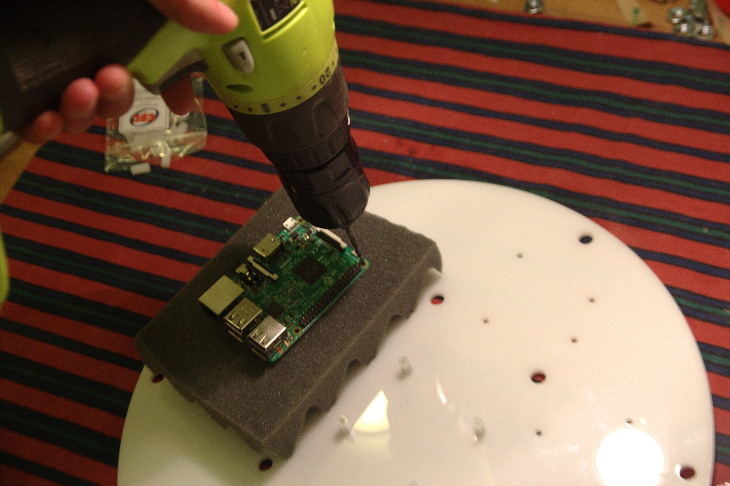 Drilling to widen the RPi mounting holes so it could be mounted on the same level as the
Arduino
Drilling to widen the RPi mounting holes so it could be mounted on the same level as the
Arduino
 RPi dust leftover (the holes were only expanded by a tiny amount in reality)
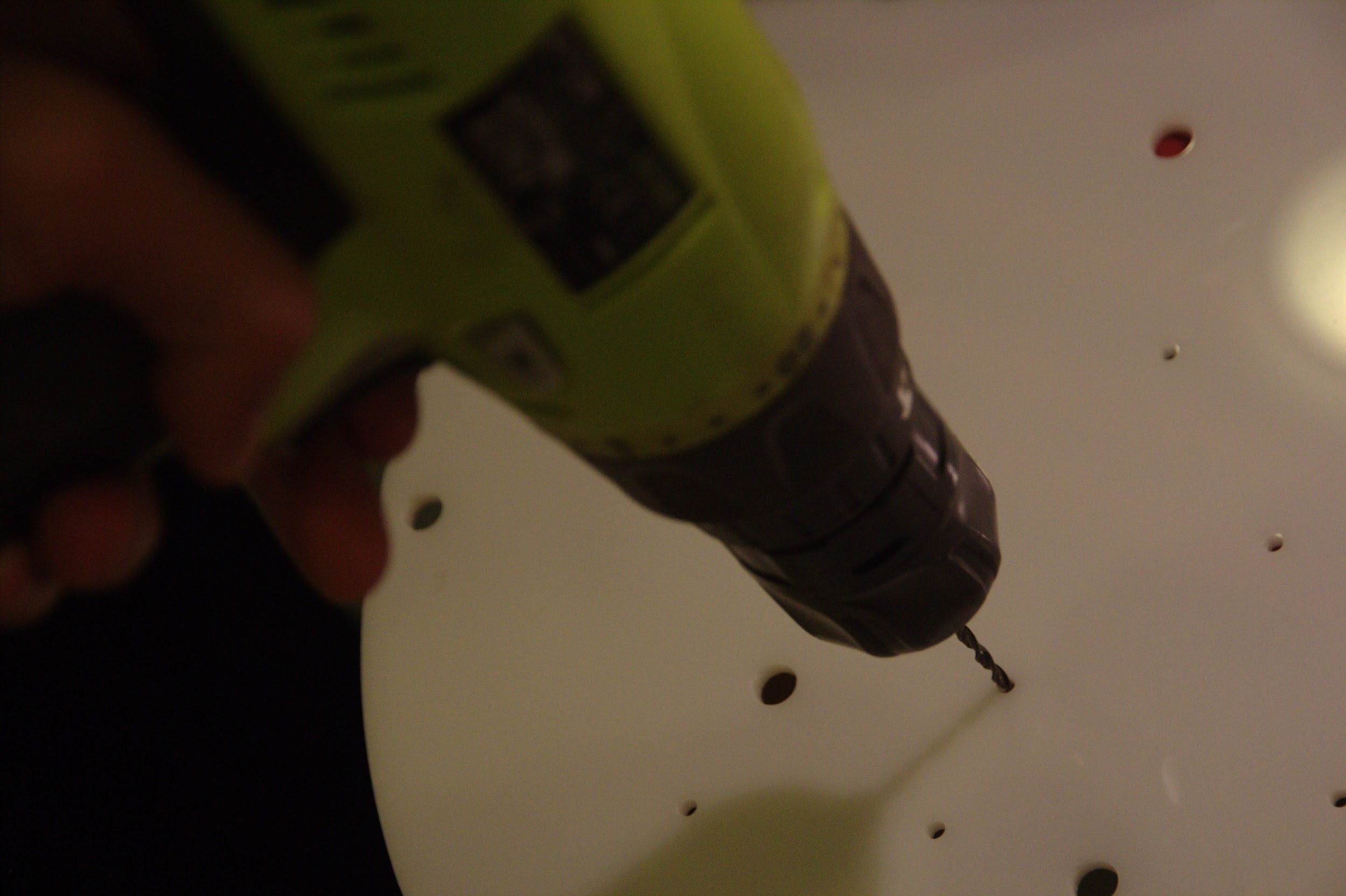 Drilling into the existing RPi mounting holes in the Perspex to widen them accordingly
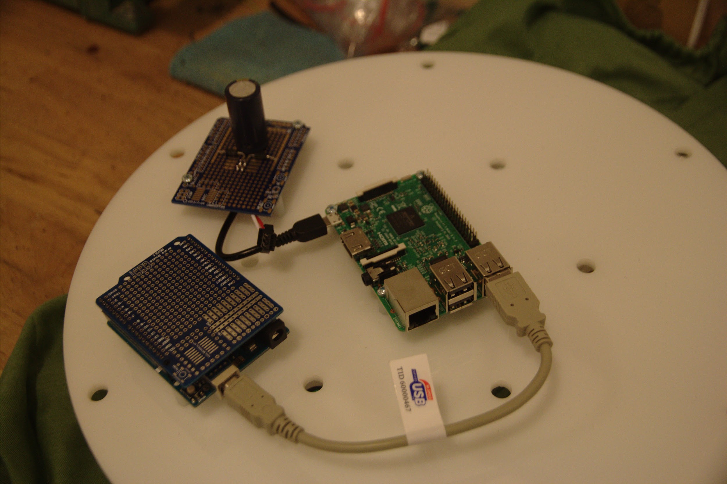
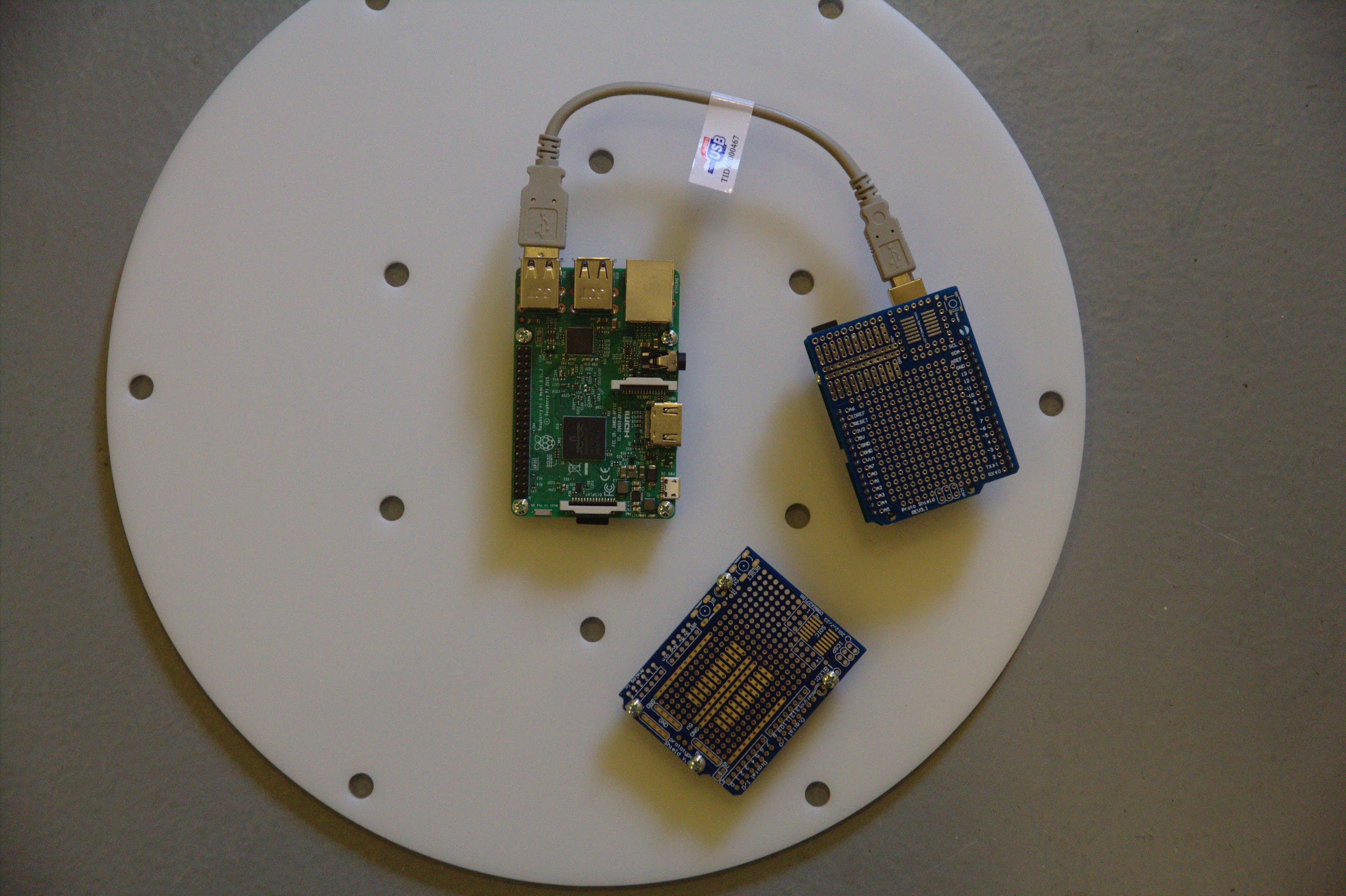 Circuit boards in their final mounting positions on the Perspex (RPi is green in the centre with a
cable attached to the Arduino, and the protoboard for delivering power is separate below)
Circuit boards in their final mounting positions on the Perspex (RPi is green in the centre with a
cable attached to the Arduino, and the protoboard for delivering power is separate below)
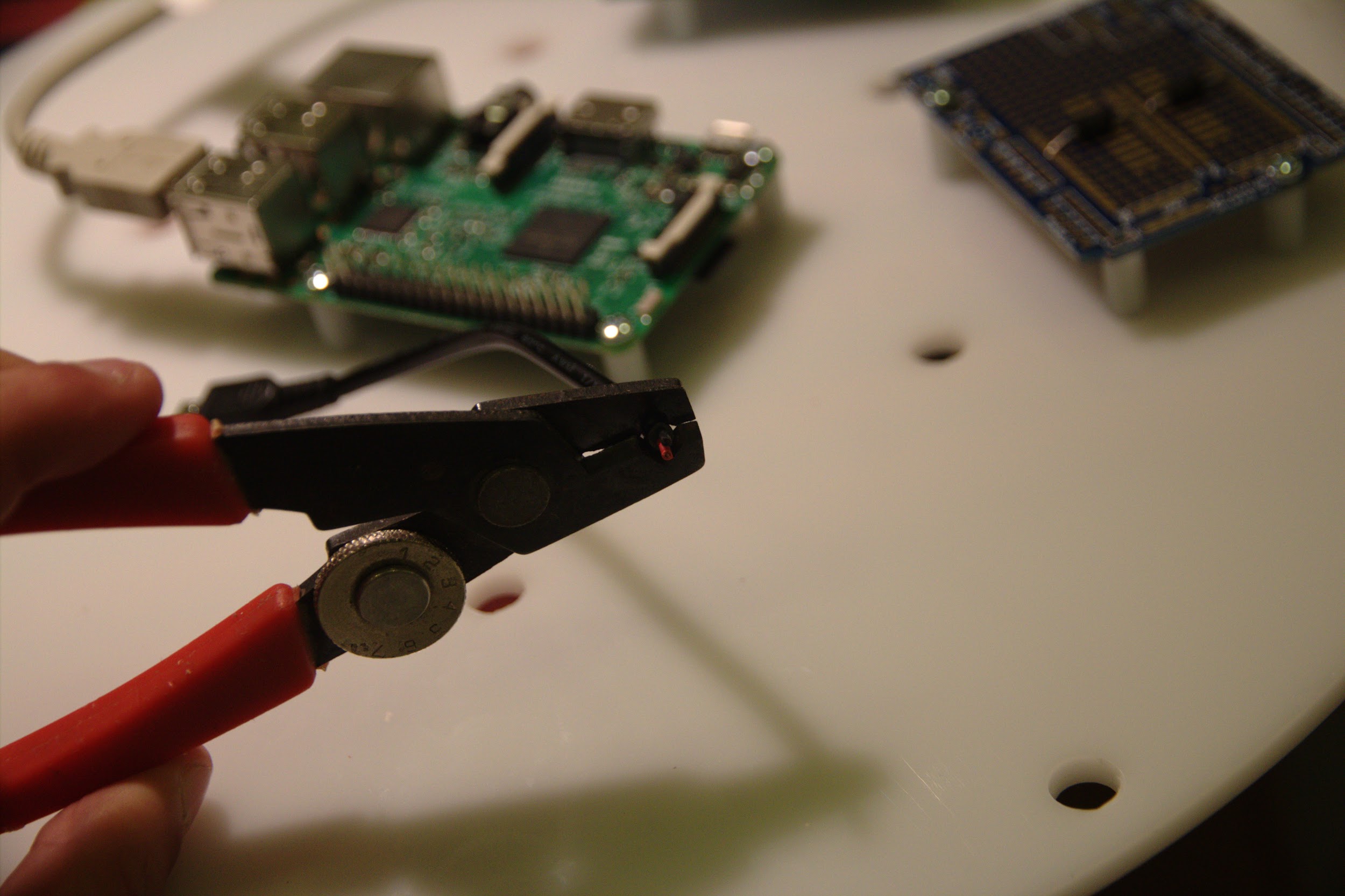
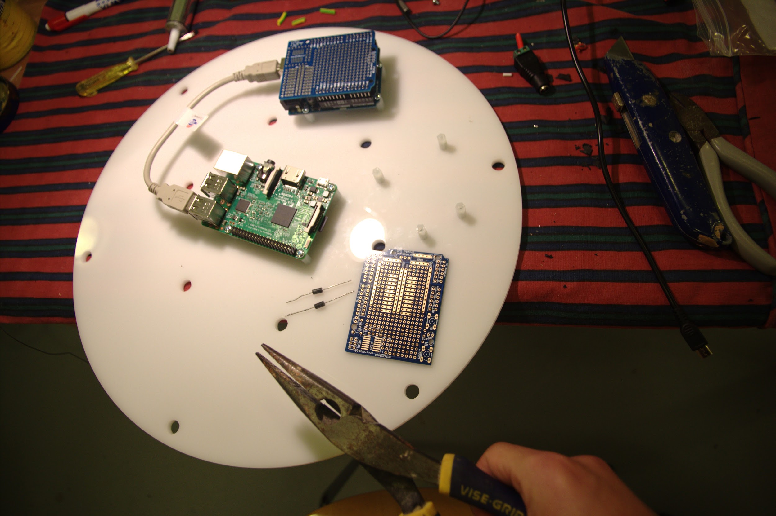 Voltage regulators desoldered from the earlier prototype and pliers to tightly bend their legs at
right angles before re-soldering them into position in the adjacent board
Voltage regulators desoldered from the earlier prototype and pliers to tightly bend their legs at
right angles before re-soldering them into position in the adjacent board
 Simulating the MicroUSB feeding power to the RPi to estimate the length of cable to cut
 Stripping off both ends of the MicroUSB cable before tinning the wire
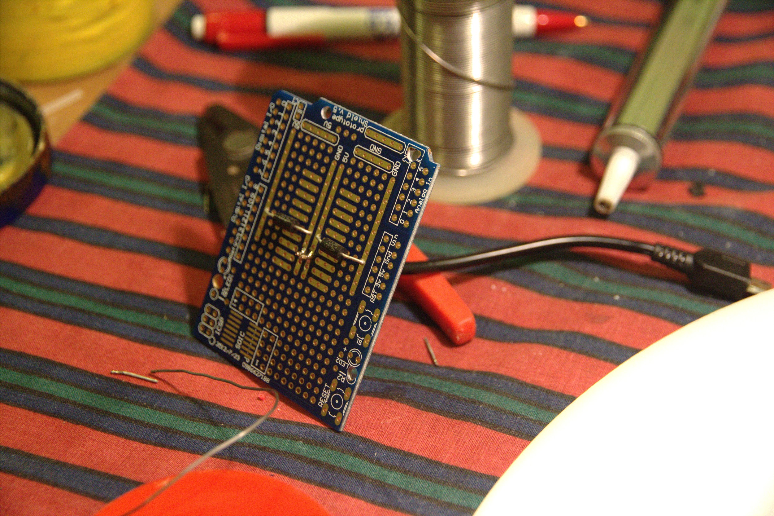 The first parts to be soldered to the power delivery board: voltage regulators and the MicroUSB
cable
The first parts to be soldered to the power delivery board: voltage regulators and the MicroUSB
cable
 Mounted power delivery board with the capacitor and LED power connector soldered
 Power connections in place, including the side of LED power that is attached to a ‘shield’
protoboard on the Arduino
Power connections in place, including the side of LED power that is attached to a ‘shield’
protoboard on the Arduino
 Links on the Arduino shield from the power, data and clock pins to where the LED connector will
go
Links on the Arduino shield from the power, data and clock pins to where the LED connector will
go
 Finished electronics for the physical piece with the LED connector (extruding above the
Arduino) that fits into a single connector to the actual LEDs hidden below
Finished electronics for the physical piece with the LED connector (extruding above the
Arduino) that fits into a single connector to the actual LEDs hidden below
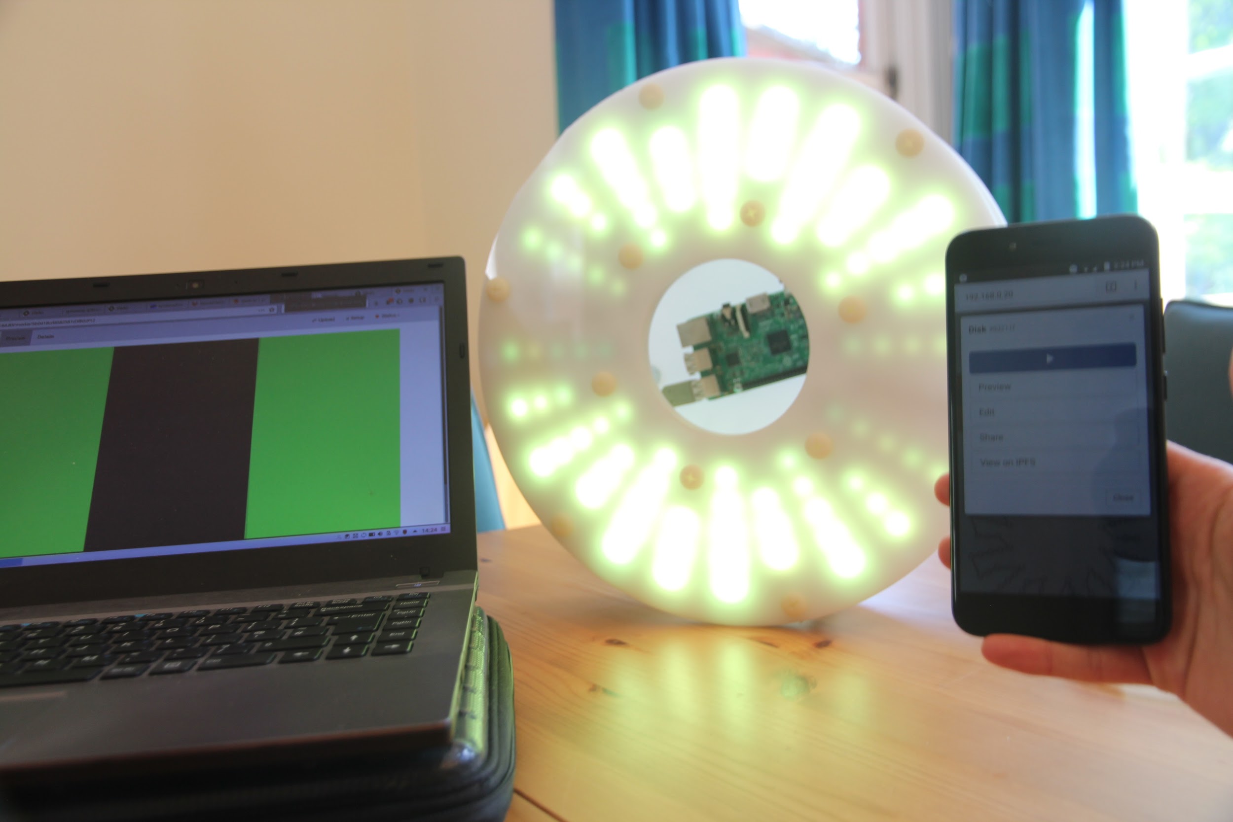 Media uploaded on the web app being displayed on the finished object