WiFi Pulse Light
In this blog I walk through the process of realising my ‘pulse light’ starting with a video demonstrating its features in action, followed by a summary of the outcome and then captioned pictures and videos to illustrate the development from beginning to end. I was inspired by LED artworks (like this: link) and smart home devices.
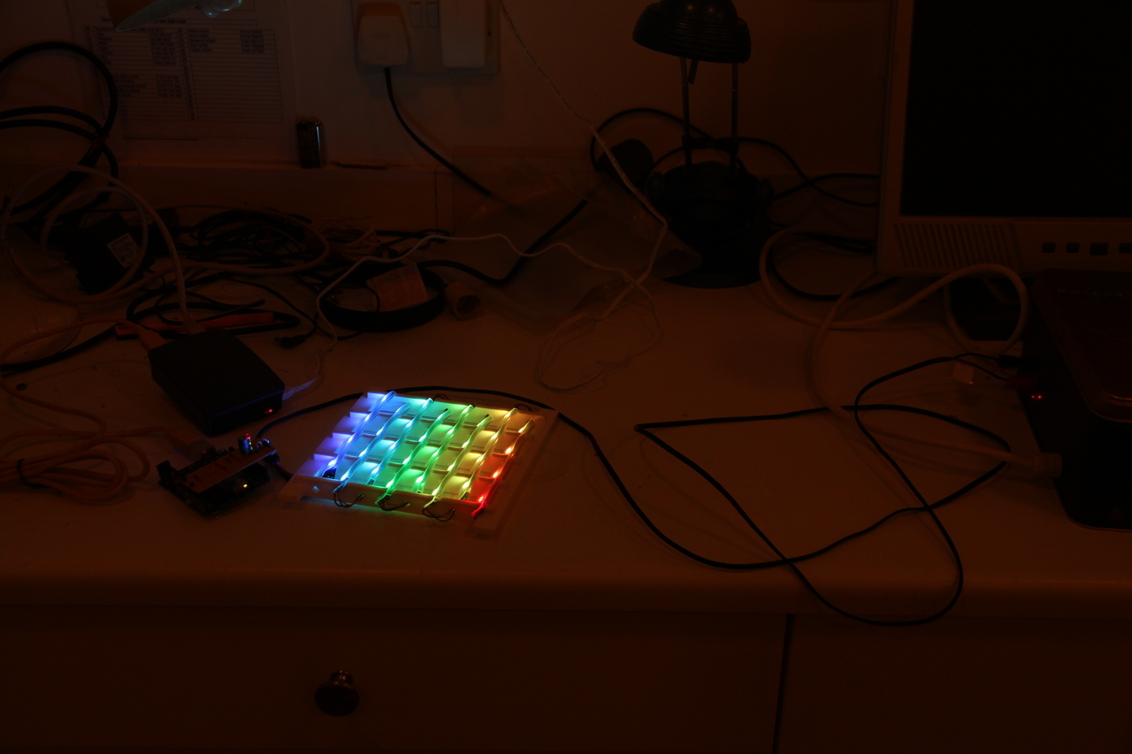
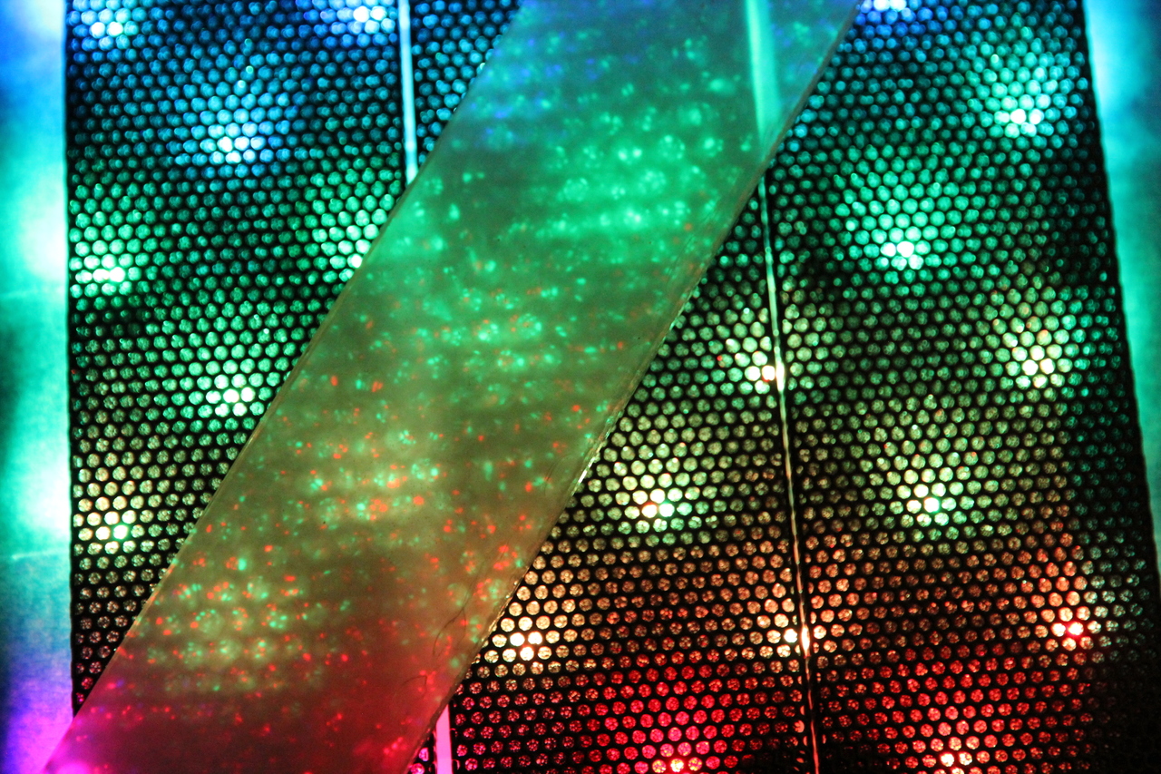
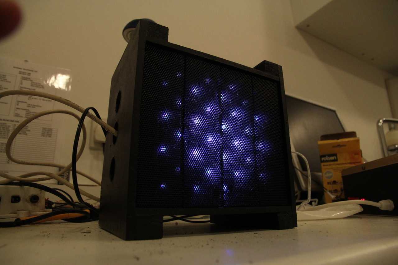
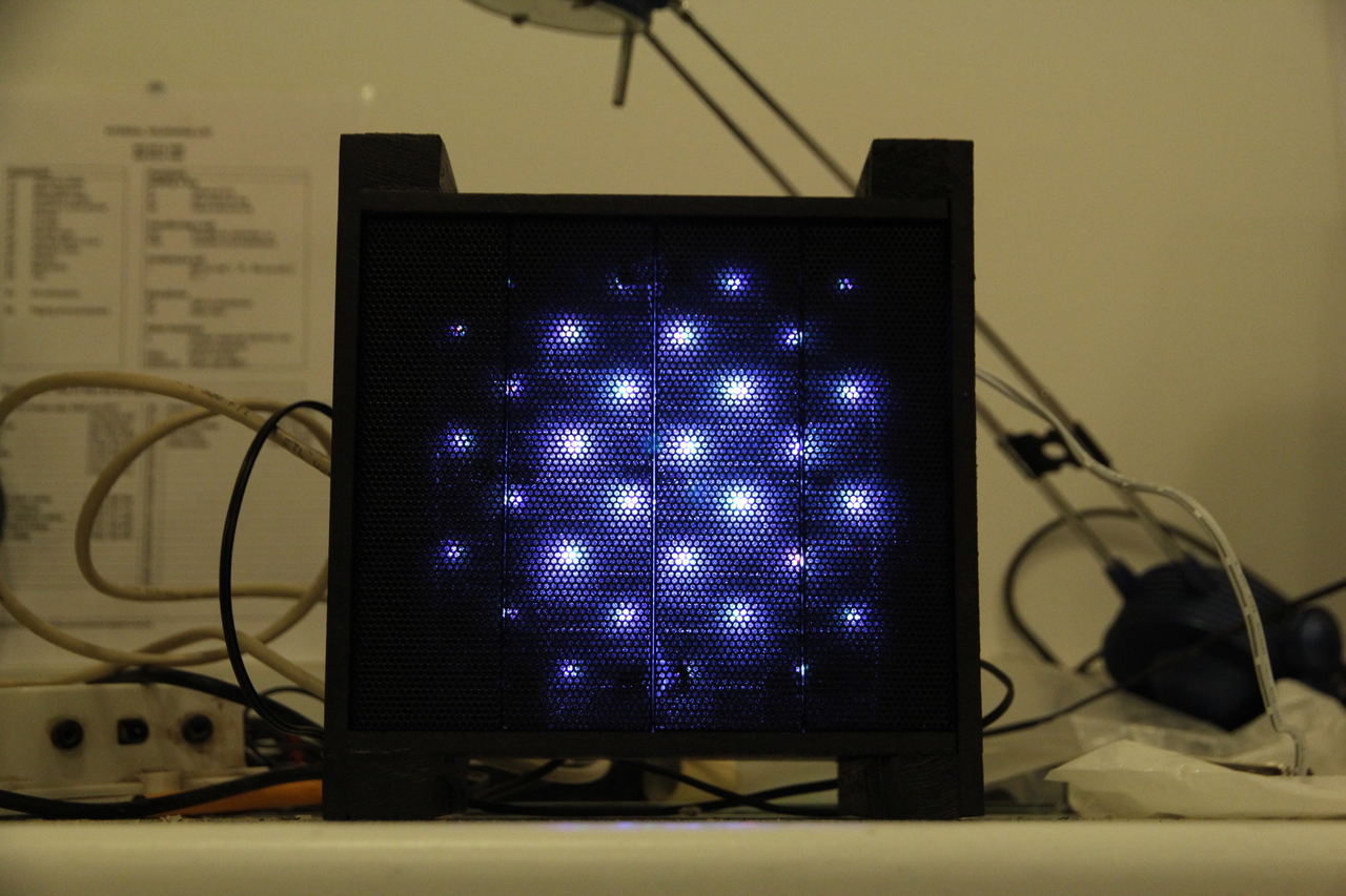
The start of the video shows a light-dependent resistor (LDR sensor) embedded into the enclosure. Next it shows the LED array behind perforated metal mesh which I recycled from my old PC. A Raspberry Pi 3 inside the cube connects to WiFi so the only two cables required are power for the RPi and LEDs.
I start the interactive stopwatch at about thirty seconds into the video above, after SSHing into the cube’s Pi from the resin.io dashboard on my laptop. The stopwatch is actually executed as a Python script:
python time.py 60 # starts a 1 minute timerWhile the script is running, the state of the timer is continuously sent from the Pi to the Arduino changing the animation pattern on the LEDs. As the timer finishes, the lights change from white to green to blue to red and the frequency of the pulsing effect increases. Finally it ends with a stimulating alarm pattern with random flashing that must be turned off by ‘activating’ the light sensor (waving your hand over it to block the light).
References
Process
The first prototype (blog here: link) powered and controlled the LED strip using FastLED on the Arduino, so my next step after that was to carry out a serial data communication test. I separated RPi logic from Arduino input/output because “[WS2812B’s] interface is very time-specific … microprocessors like those on the Raspberry Pi can’t give you a reliably-timed pulse” (source: link).
The serial communication test was built on these examples:
At this point I also installed ResinOS on the RPi, which allows everything to be programmed remotely in a Docker container. The snippet below shows how I installed Python dependencies on the RPi Docker:
# Dockerfile
RUN apt-get update && apt-get install -y \
    python \
    python-dev \
    python-pip \
    python-virtualenv \
    --no-install-recommends && \
    rm -rf /var/lib/apt/lists/*
RUN pip install pyserial
Once successful I filmed the setup, showing Arduino printing bytes it recieves from the RPi across the LCD:
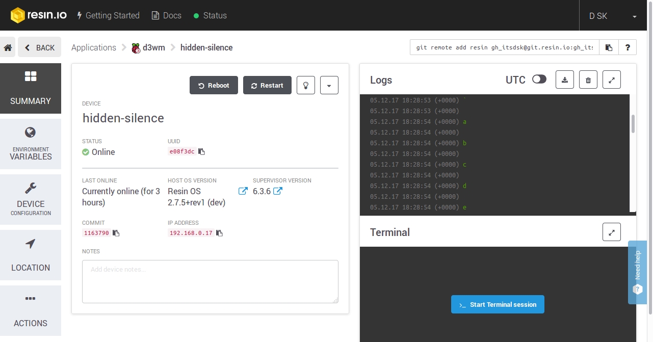
Logs showing characters being returned from the Arduino to the Pi in the test above
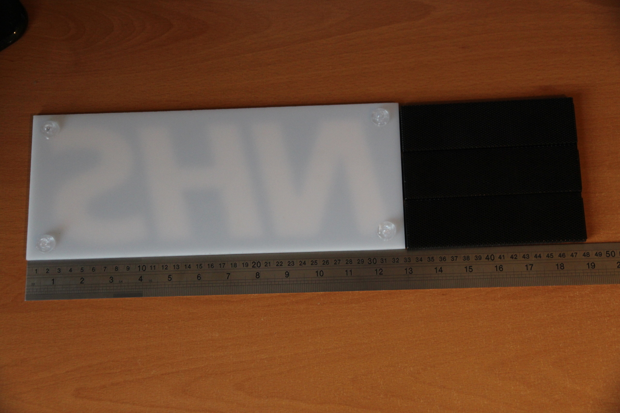
Assessing different recycled materials
I sketched designs based around two objects I found to fulfil the goal of recycling materials - an NHS sign and spare PC case parts. I wanted to diffuse LED light using both but couldn’t detatch four nodules stuck to the back of the NHS sign. So in the end I could only incorporate the black mesh panels into the design. Also I wanted to maximise the space inside to fit components while reducing the bezel around the ‘display’, so inspired by the Lloyd’s building, London and Bowellism I designed the enclosure to have an inside-out design with the supporting structure visible externally.
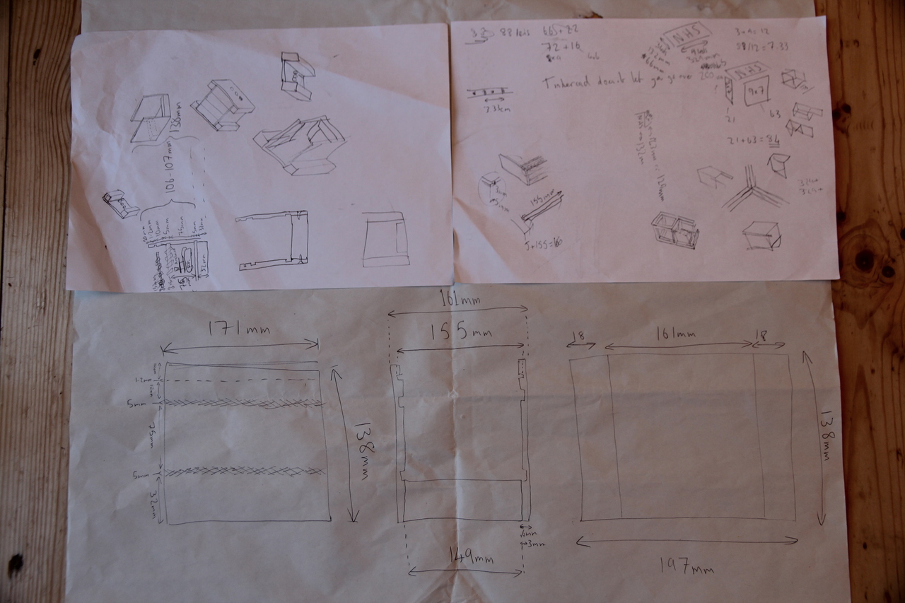
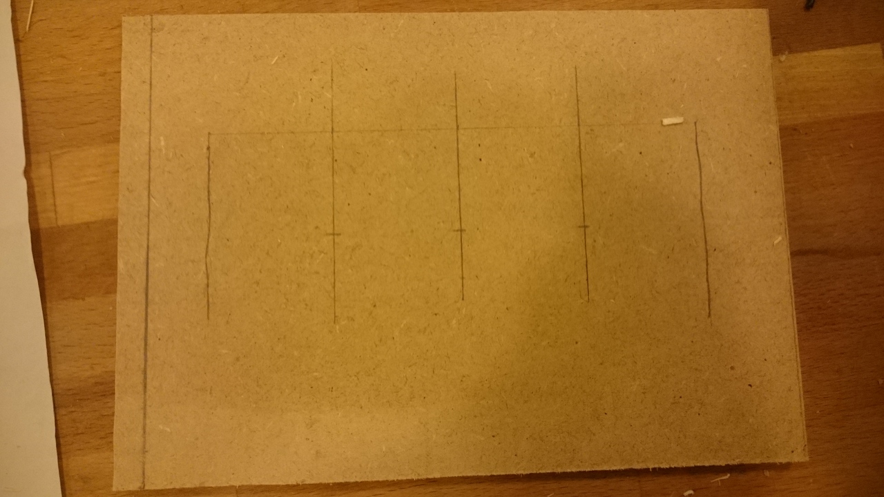
The A4 sheets show some of my notes and sketches, while the paper below contains the designs for the final enclosure.
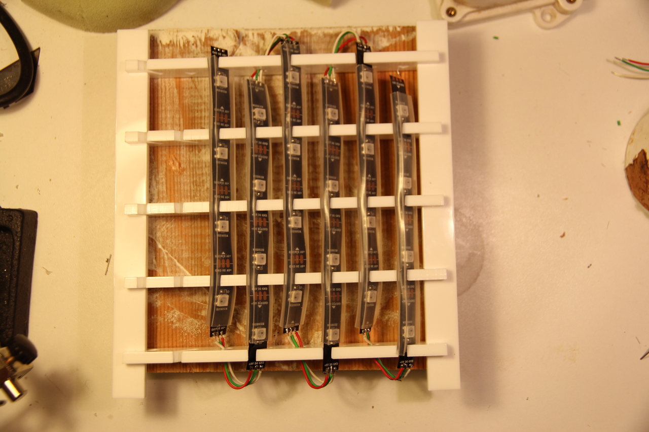
Only about 32 lights fit in the small area behind the mesh because the strips have just 30 LEDs per metre. It would be difficult to see patterns in such low resolution, however I thought of a work-around by physically trying things out; offsetting the position of each strip. This way the same number of LEDs can effectively display greater detail; forming 8 columns instead of 4.
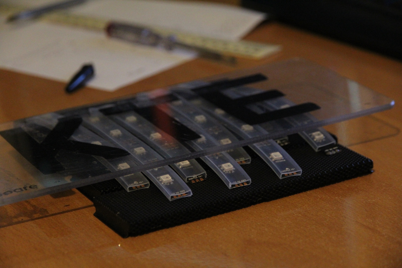
Trying out LED configurations
Using computer-aided design (Inkscape vector software) and computer-aided manufacture (laser cutter) I precisely fit the LED-holding ‘lattice’ to the WS2812B strips and recycled metal grating. I also rotated each strip within the lattice aiming to improve the fit and further reduce glare. It could have been either acrylic or wood which I would’ve prefered because it’s renewable. But considering heat dissipation (each WS2812B consumes up to 60mA getting quite warm) I compared both material’s heat capacity and found acrylic was the best option for avoiding fire risk.
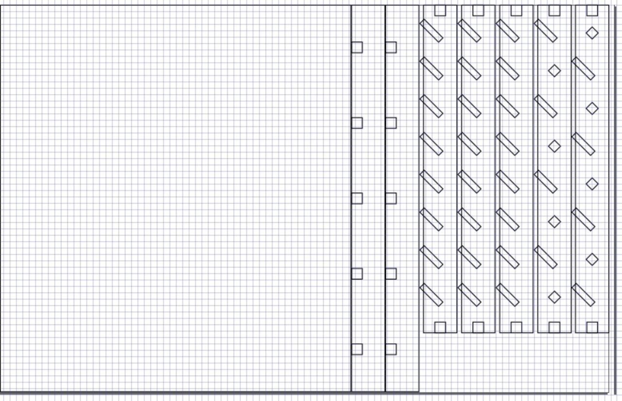
Vector design for the LED lattice
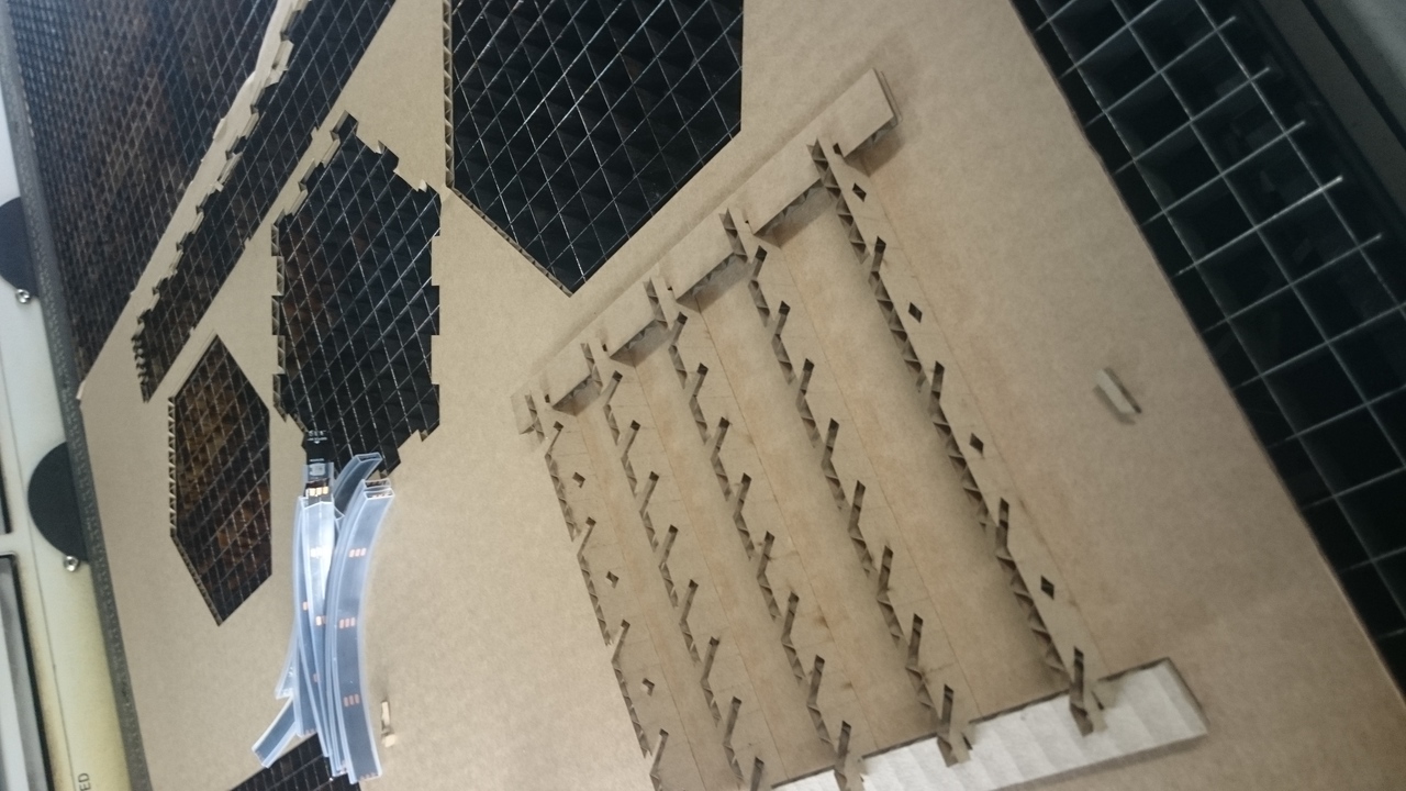
Checking measurements first by cutting cardboard
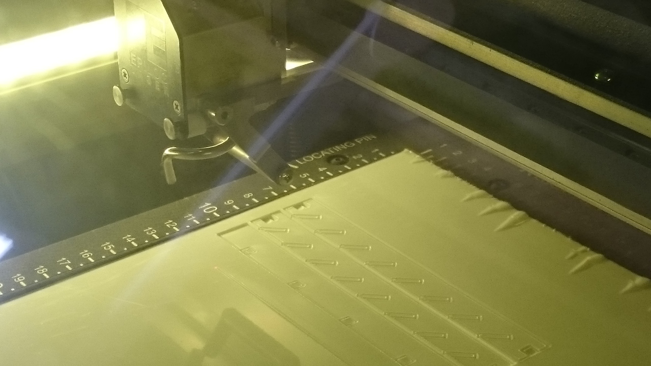
Laser cutting acrylic sheet
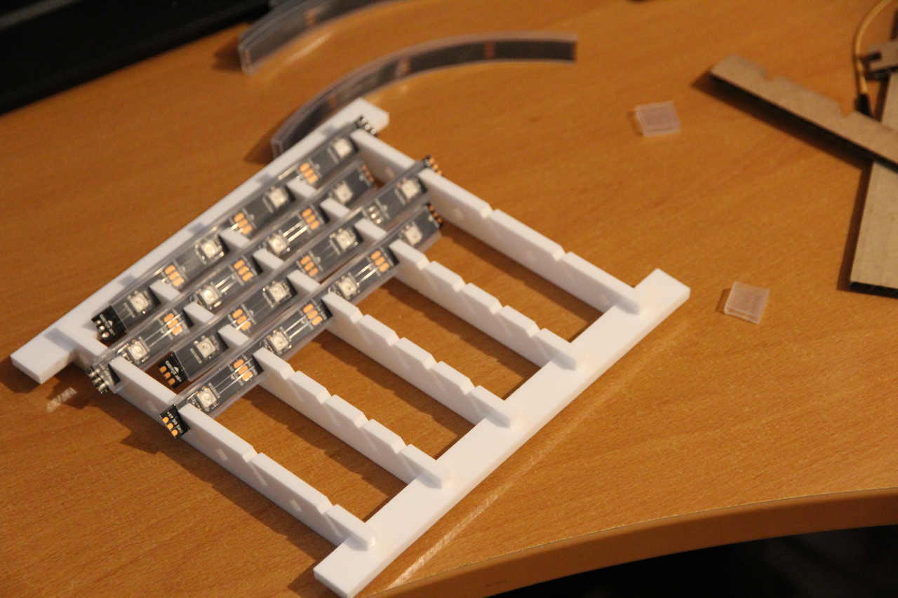
Fitting LED strips after separating and assembling the lattice parts
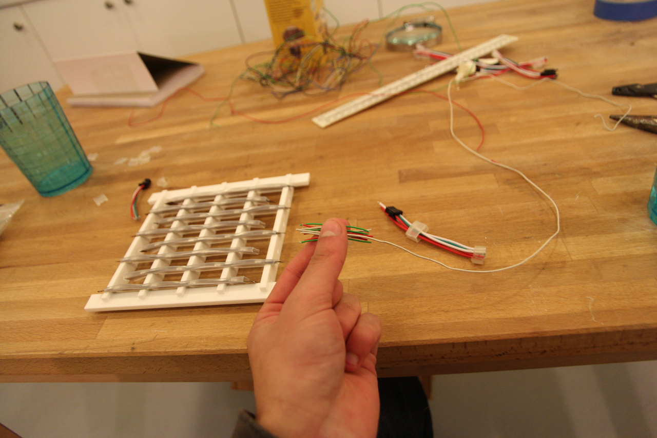
Cutting equal length colour-coded wire segments to neatly link the strips together
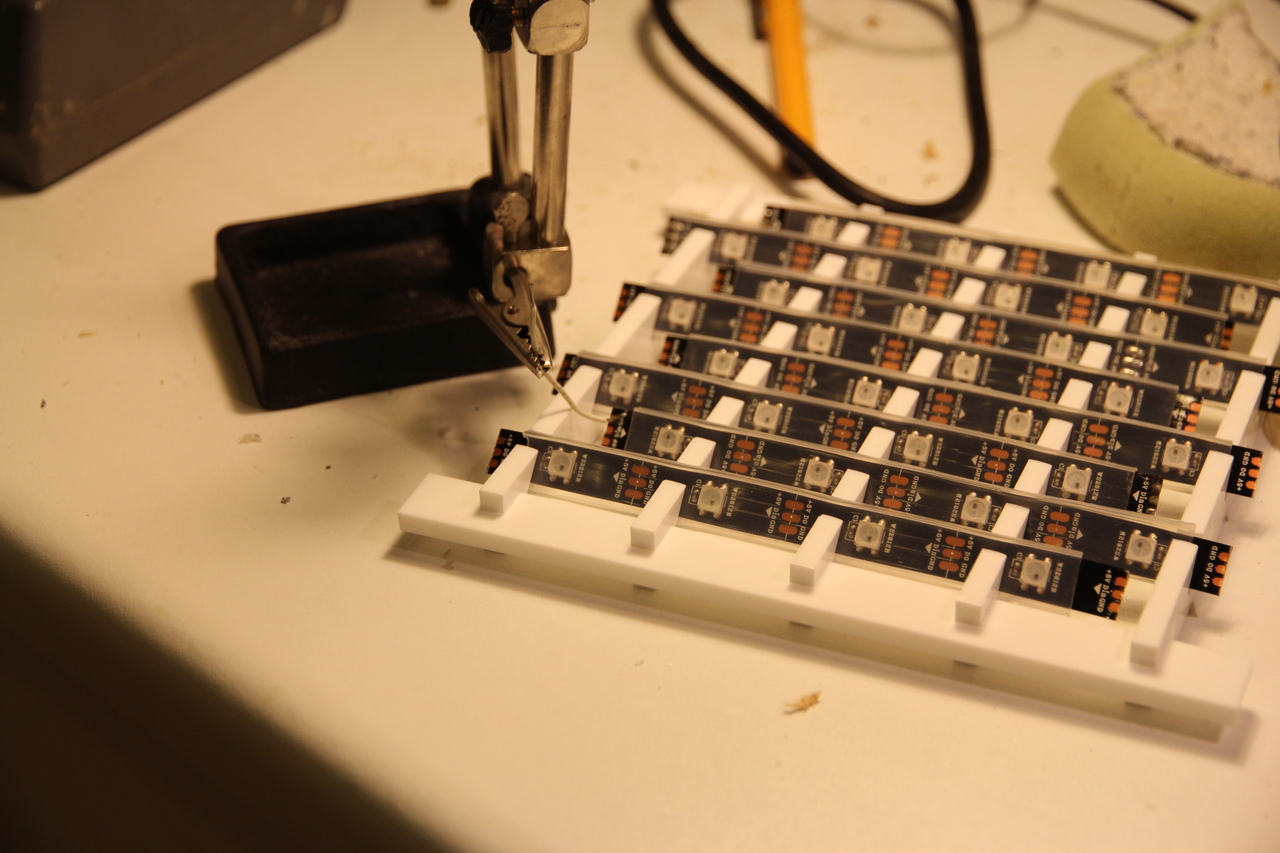
Trying to solder the first strip with some mechanical help
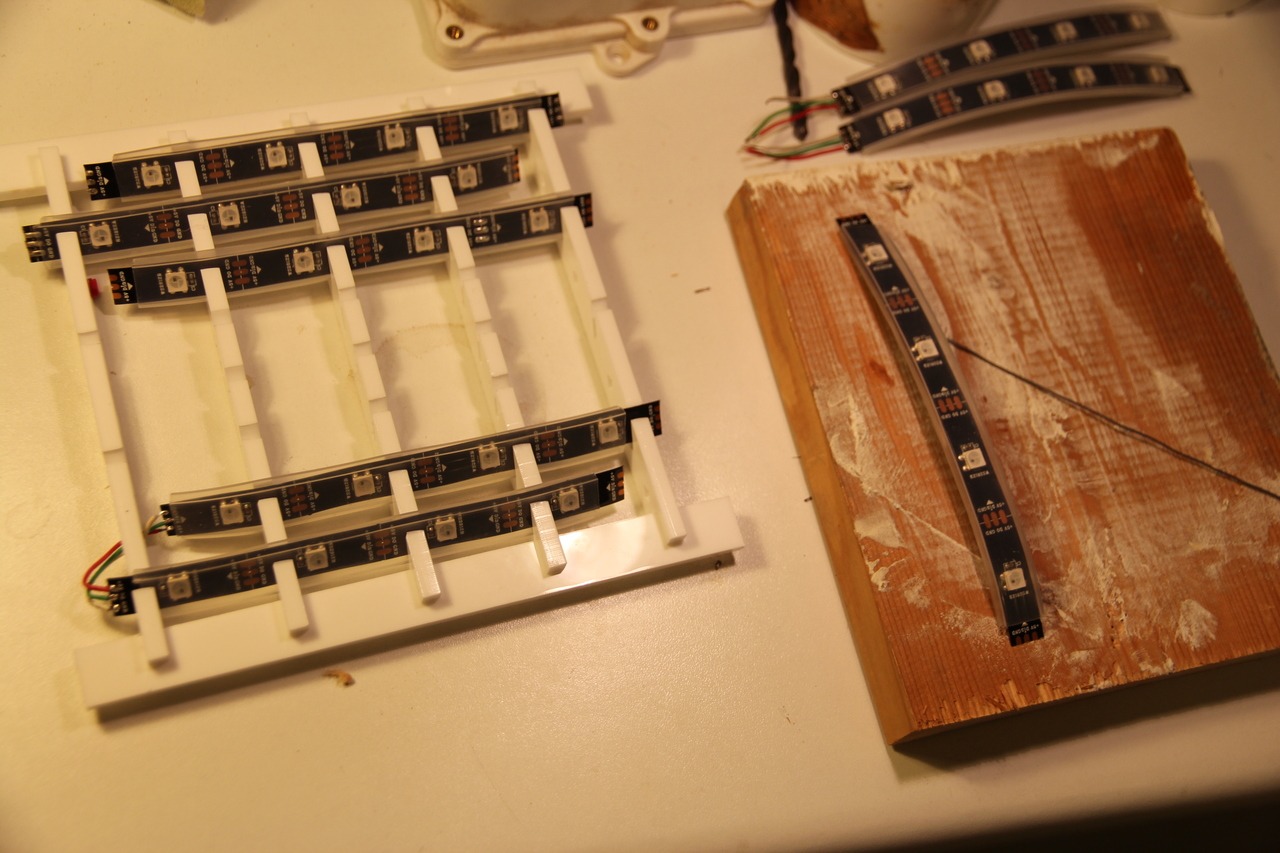
Removing the strips was a better soldering strategy because the wires had to be threaded through small holes in the ends of the lattice
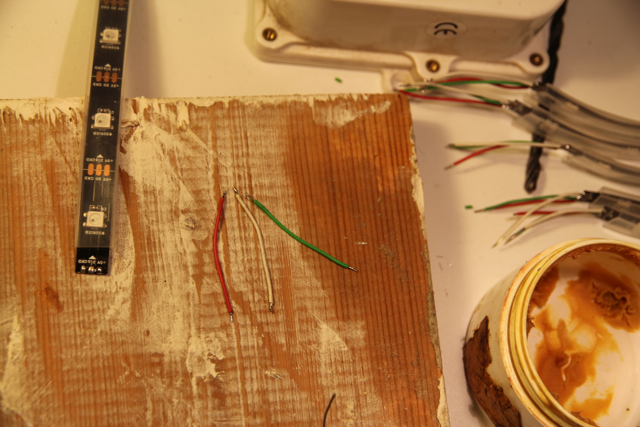
Applying flux and tinning all the connections to help soldering
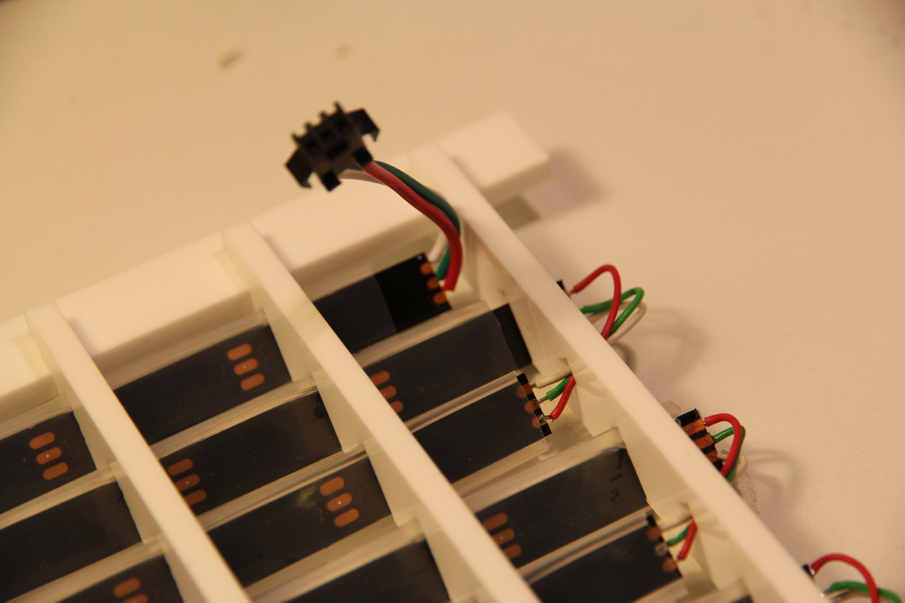
Modular connector so the lattice is detachable
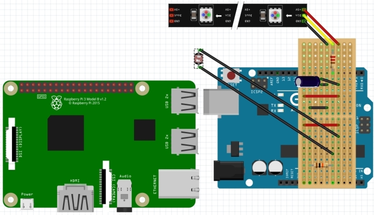
Schematic for the final electronics with an imaginary USB cable connecting the Pi and Arduino (made on ‘Fritzing’)
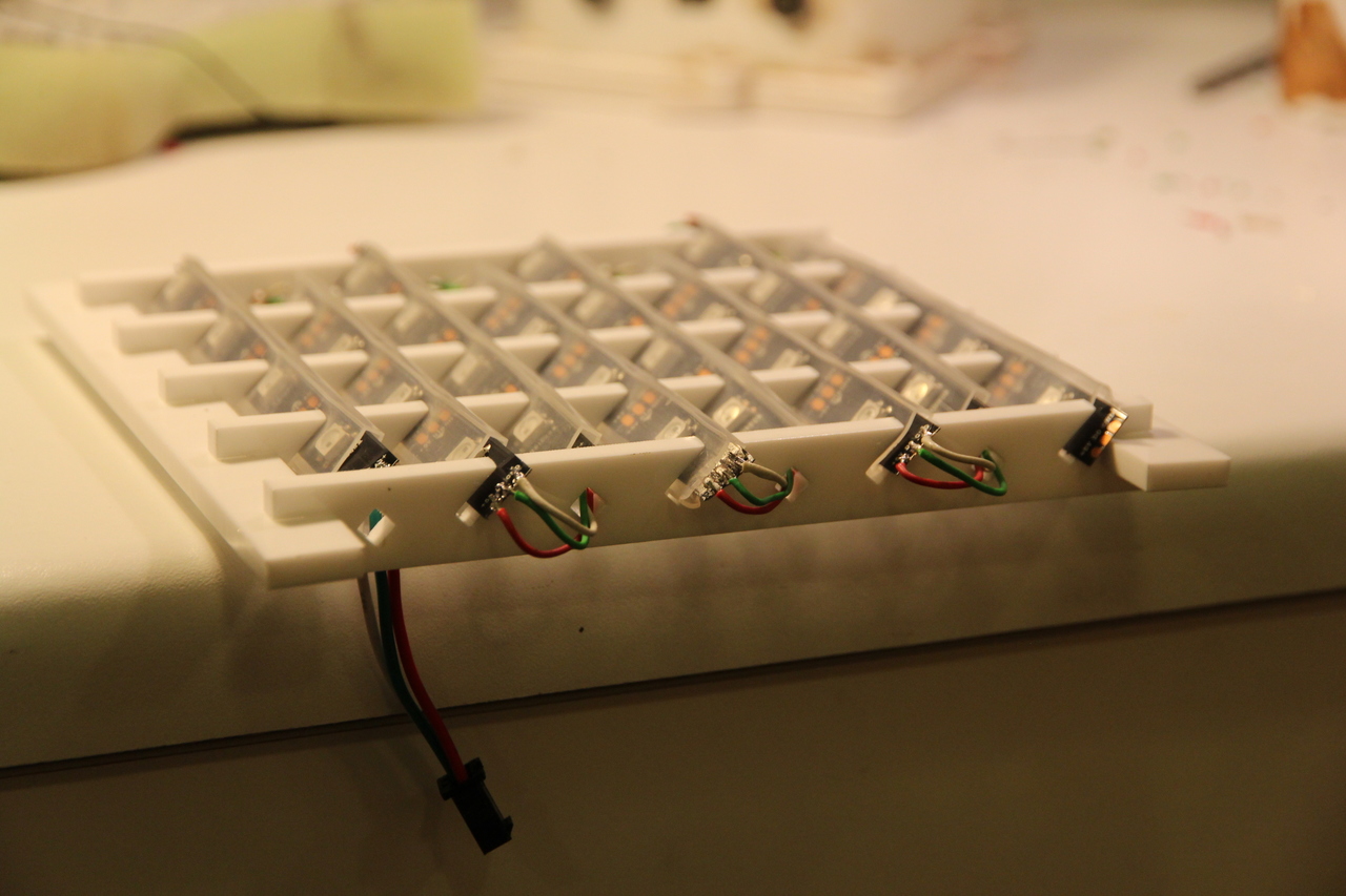
Confirming none of the LEDs were broken during the fiddly assembly
After finishing the LED lattice and getting Pi <-> Arduino communication to work, I connected them in incremental tests shown in the videos below. One problem was how unstable the LDR reading was - even in consistent lighting it changed randomly. I tried helping it on the Arduino by sending an average of readings instead of the instantaneous reading, but this incurred performance issues lagging out the LED patterns. So I tried storing every reading on the Pi then calculating the mean average brightness during the timer countdown. That approach had other issues so I ended up removing a lot of code, then ended up with a simple but effective-in-practice solution. In the final piece the analog LDR reading is constantly sent to the Pi while the timer is active and when the countdown reaches zero the Pi waits for a reading that is sufficiently lower than the lowest reading so far. Other issues I overcame include correctly mapping patterns to the LED matrix, checking bytes recieved were valid and maintaining state on both sides of the USB cable.
Putting data communication and LED lattice together with LDR sensor
More effects but notice the jump/lag in the animation when the timer starts
Bug that disabled half the strips, introduced while trying to reduce work done by Arduino by not calculating colour where there isn’t an LED
Unfortunately I couldn’t find enough frosted glass to cover the lattice with this interesting effect
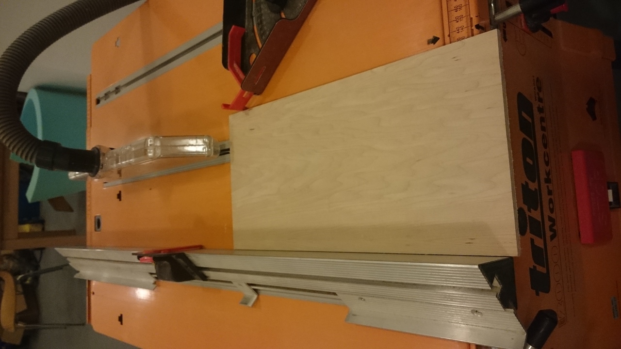
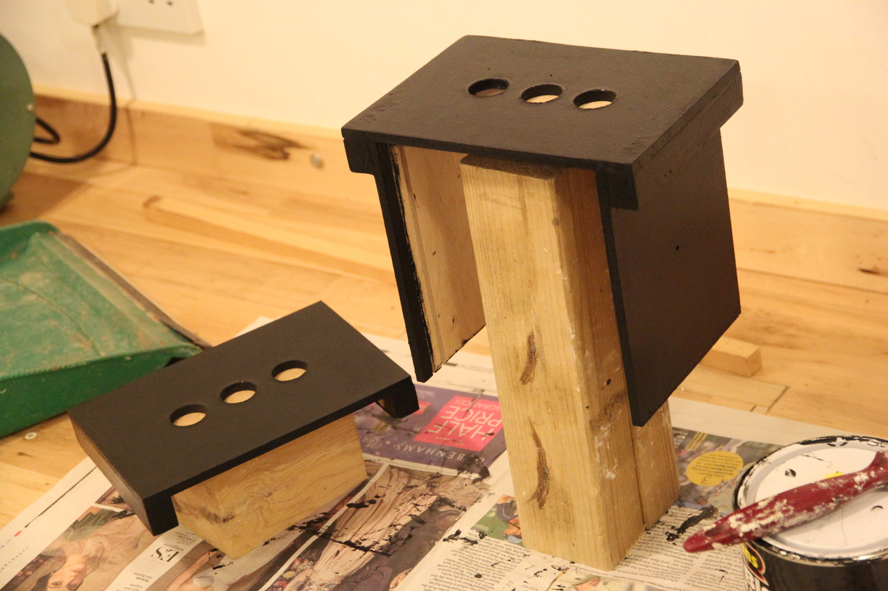
Bench saw to cut enclosure panels down to size
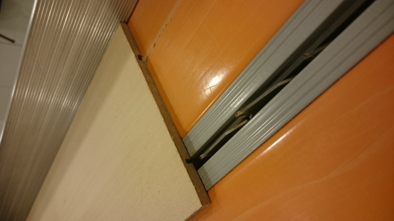
Adjusted bench saw to cut grooves (in order to shelve the metal mesh, LED lattice and Arduino/RPi tray)
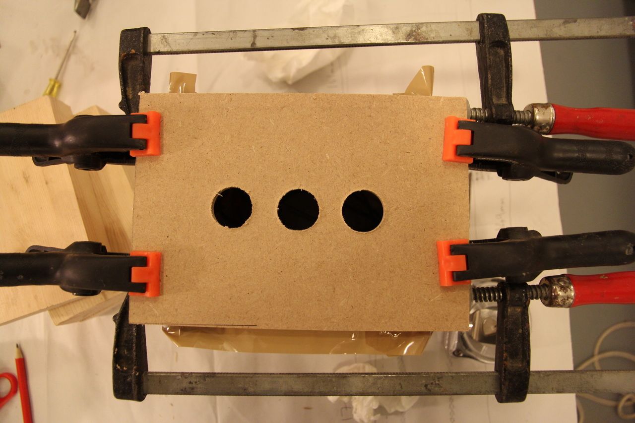
Marking points in the middle of the side panel to fit cables through
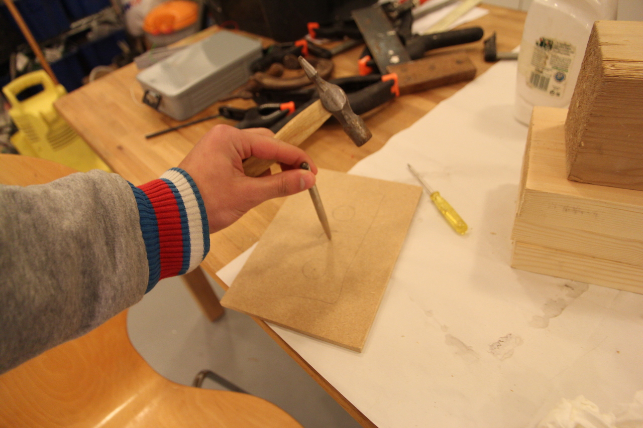
Punching indents to guide the drill
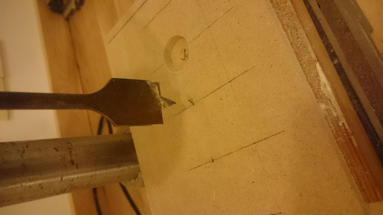
Pillar drill in action
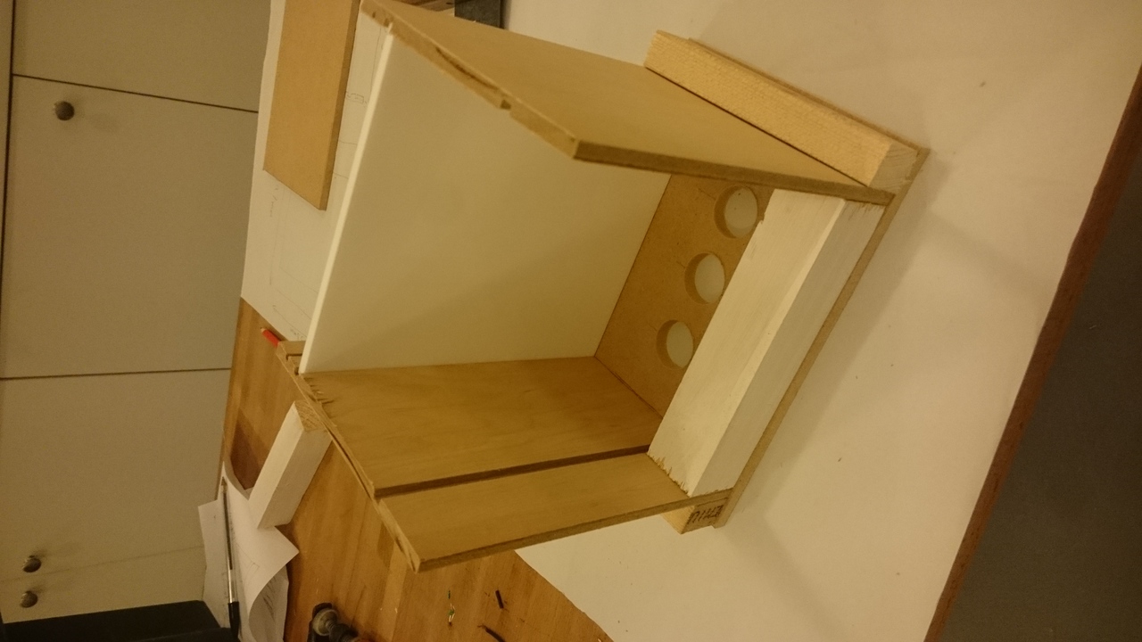
Checking parts still fit before the final (and irreversible) assembly
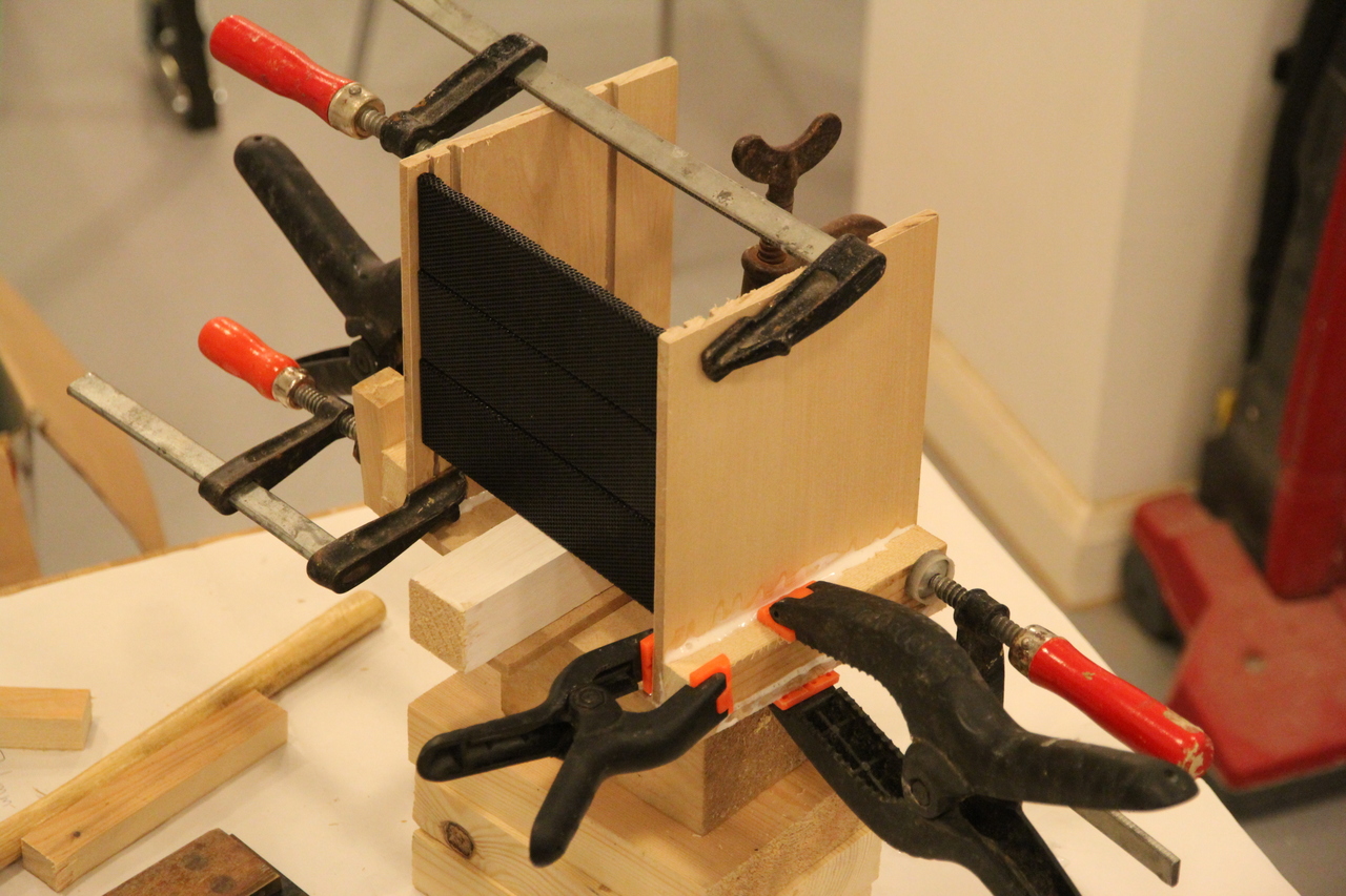
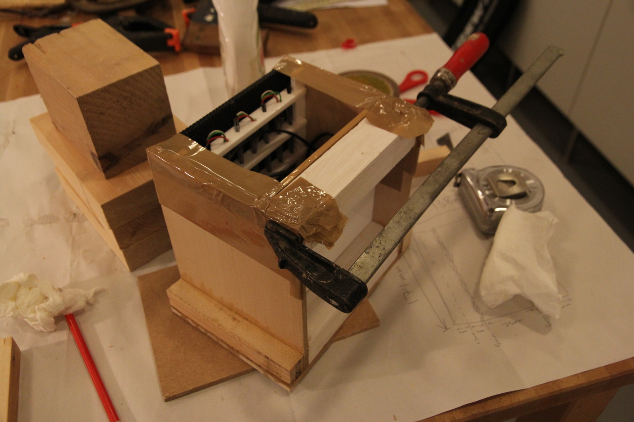
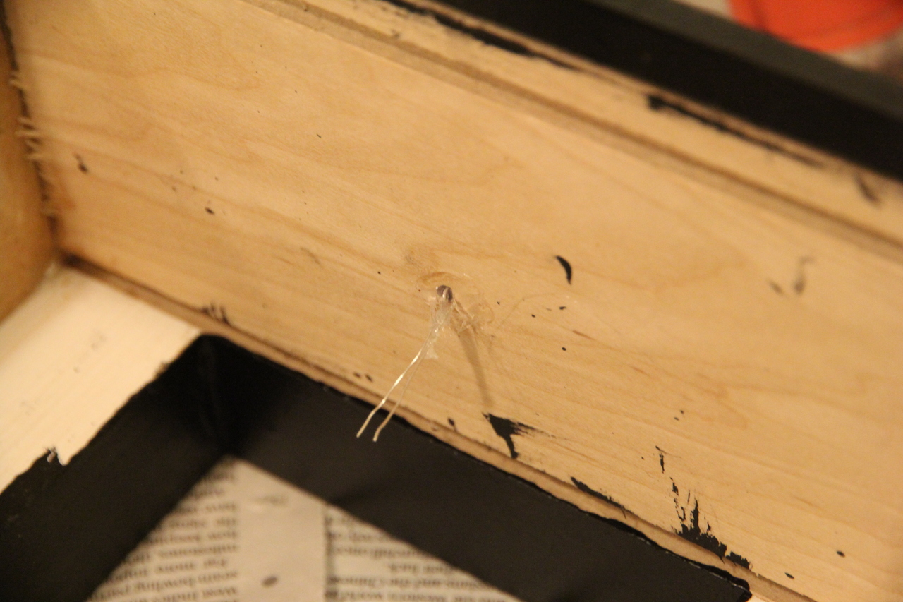
Securing together one half of the enclosure with PVA glue and tight clamps
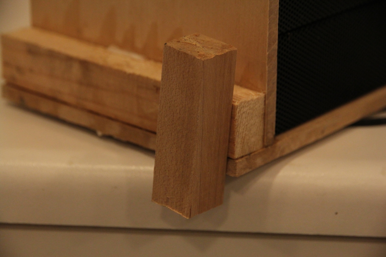
Half the enclosure in place 12 hours later - I accidentally glued on this random block of wood that was positioning one of the clamps
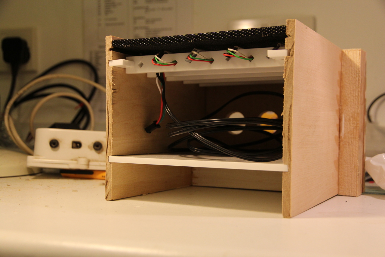
Checking the internals fit after carefully pulling the random block of wood off
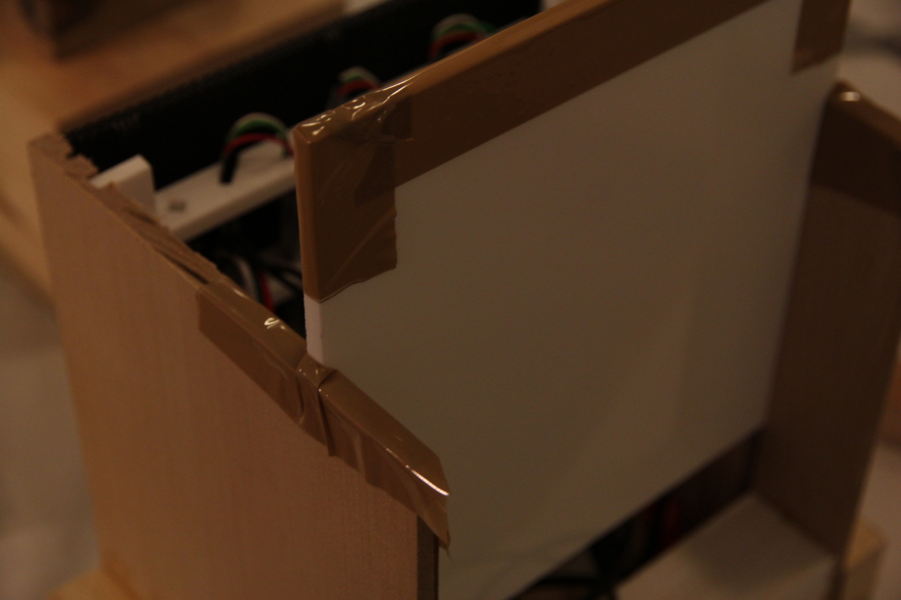
Taping edges of the enclosure that will slot into each other to stop them accidentally bonding like the random block of wood did last time
More gluing, ensuring everything fits by clamping around the internal components
Second half of the enclosure glued and clamped in place
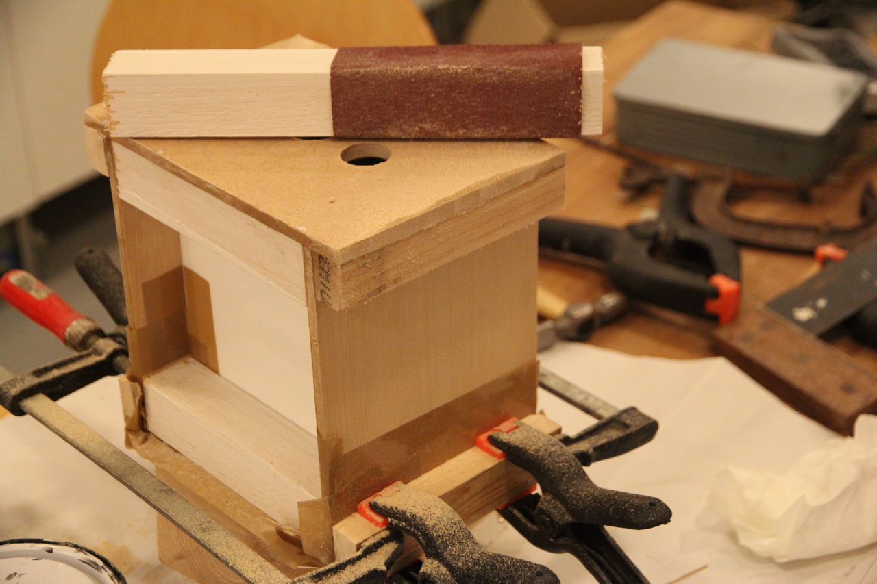
Sanding down rough edges to improve finish for the paint
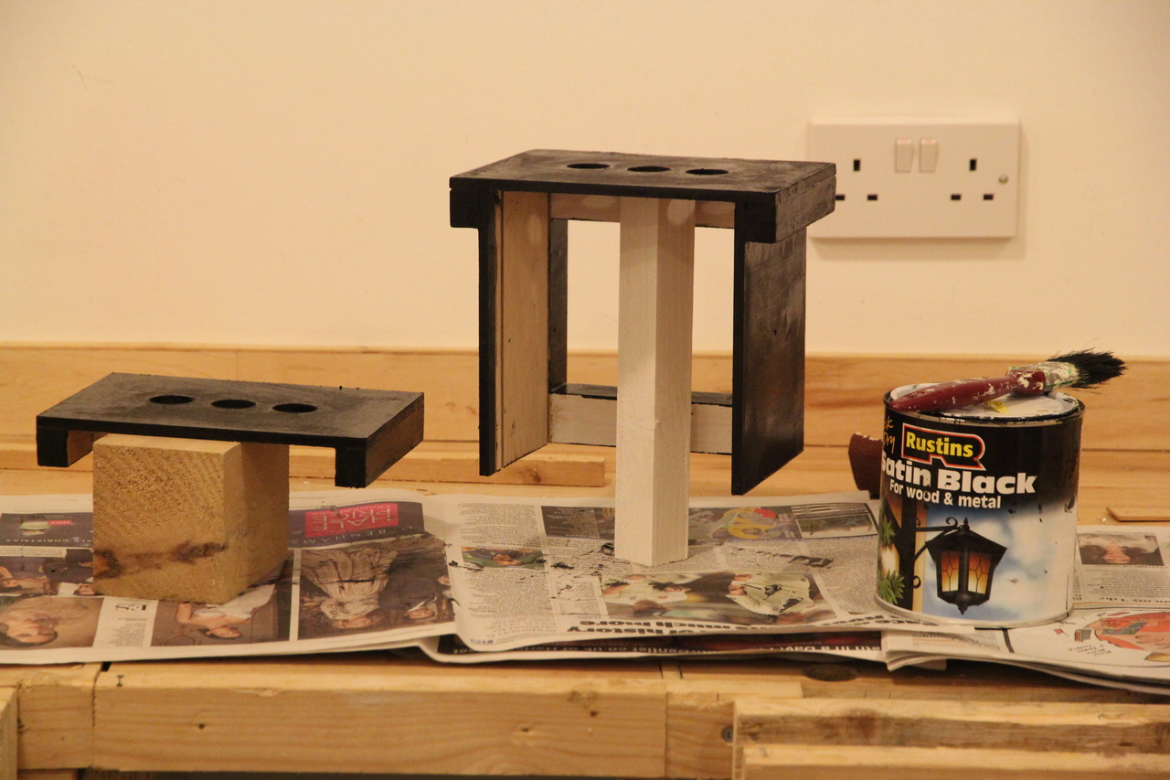
Paint on externally visible surfaces, I left the inside unpainted to see the Arduino/RPi/lattice
Second layer of paint after the first dried
Light dependent resistor (LDR) inserted backwards and hot glue gunned in place
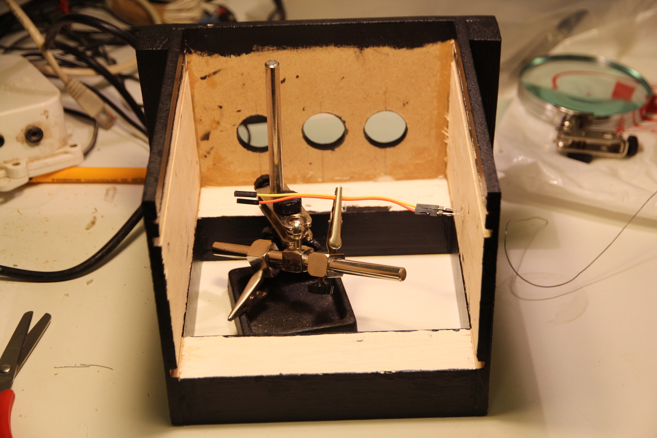
Soldering modular connections to the LDR sensor so the Arduino can be easily connected and disconnected
Ta da!
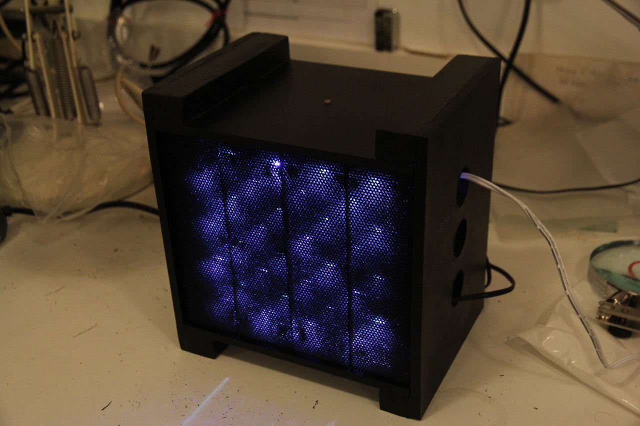
Originally the concept was to build a light for living spaces that makes use of analog interactivity. For the most part I think it successfully achieved its aims however the final result failed on one element of the minimum viable product (MVP): self-containment. In order to keep the size down and get as close to my MVP as possible within the allocated time I ended up reusing a biscuit tin power supply from a previous project instead of integrating a new one. In the future the practicality of the timer could be worked on, but I really want to mount a hard drive inside it and turn it into a LED network attached storage device that warns when a backup is due.
Finally a video showing it disassembled…
For Physical Computing (IS53030B)…